Cub Cadet PRO Z 972S KW Operation Manual - Page 24
Replacing the PTO Belt, Replacing the Deck Belt, Replacing the Blades
 |
View all Cub Cadet PRO Z 972S KW manuals
Add to My Manuals
Save this manual to your list of manuals |
Page 24 highlights
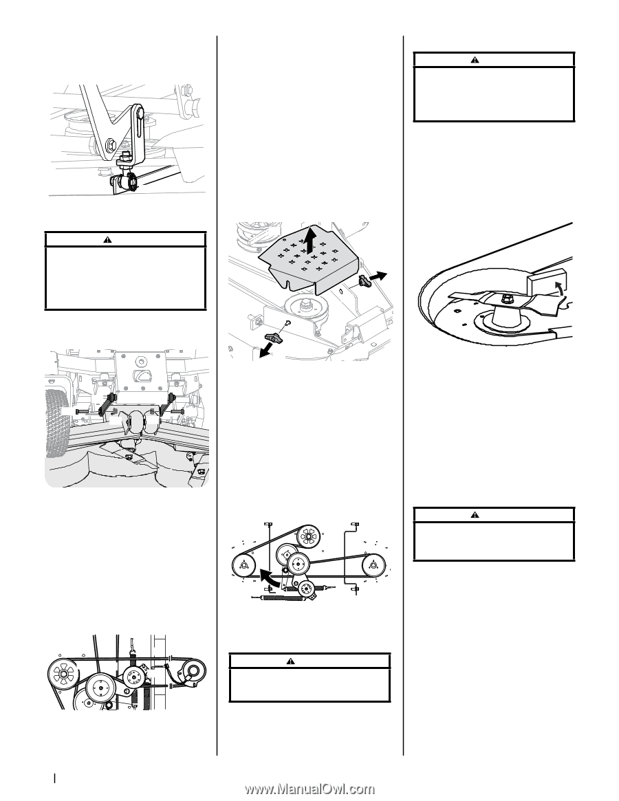
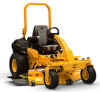
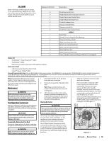
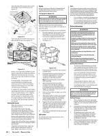
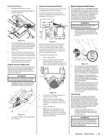
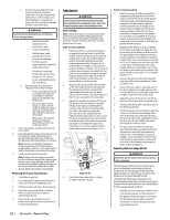
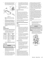
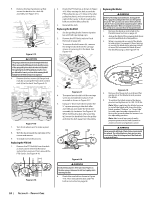
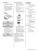
5. Remove the four lynch pins (a) that secure the deck to the deck lift assembly. See Figure 4-14. (a) Figure 4-14 CAUTION The spring is under tension due to the weight of the deck. When removing the lift linkage from the deck the tension of the springs will go from the deck to the deck lift pedal. Not capturing the deck lift pedal by placing the clevis pin behind the lowest position while removing the lift linkage from the deck will cause it to snap back. 6. Remove the hex screws (a) flange lock nuts (b) securing the front deck control rods (c) to the deck. See Figure 4-15. (c) (a) (b) (c) (a) (b) Figure 4-15 7. Turn front wheels as if to make a pivot turn. 8. Shift the deck toward the right side of the mower and remove. 9. To install reverse the process. Replacing the PTO Belt 1. Remove the PTO belt (a) from the deck as instructed in the Deck Removal section then remove it from around the PTO clutch. See Figure 4-16. (a) (b) (d) (c) Figure 4-16 2. Route the PTO belt (a) as shown in Figure 4-16. After routing the belt around the PTO pulley (b), use a 1⁄2" drive in the idler pulley bracket (c) and turn towards the right of the tractor to finish routing the belt around the idler pulley (d). 3. Reinstall the deck. Replacing the Deck Belt 1. Set the parking brake. Remove ignition key and both spark plug caps. 2. Remove the PTO belt, (refer to Deck Removal on page 24). 3. To remove the belt covers (a) , remove the wing knobs (b) from the carriage screws (c) securing it to the deck. See Figure 4-17. (a) Replacing the Blades WARNING Before performing any maintenance, disengage the PTO, engage the parking brake lever, turn the ignition key to the "OFF" position and remove the key from the switch. Protect your hands by using heavy gloves when handling the blades. When servicing the mower deck, be careful not to cut yourself on the sharpened blades. 1. Remove the deck as instructed in the Deck Removal section on page 24. 2. Jack up the front of the mowing deck about one foot and block it in that position. 3. Wrap a rag around one end of the blade (a) and grasp it to prevent it from turning, or secure the blade (a) by placing a block of wood (b) between the blade (a) and the deck housing (c). See Figure 4-19. (b) (c) (c) (c) (d/e) (b) (a) (b) Figure 4-17 4. The speed nut should hold the carriage screw (c) and tab bolt in place, if not re-install as shown in Figure 4-17. 5. Using a 1⁄2" drive insert the end into the 1⁄2" square opening in the deck idler assembly (a) and rotate the deck idler assembly (a) clockwise. See Figure 4-18. While holding the deck idler assembly (a), loosen the deck belt from the pulley and slide the belt away from the pulley. (a) Figure 4-19 4. Remove the flange lock nut (d) and flat washer (e) at the blade (a) and remove the blade. 5. To replace the blade reverse the above process and tighten nut to 100-130 ft-lbs. Note: When replacing the blade, be sure to install the blade with the side of the blade marked ''Bottom'' or "Grass Side" (or with a part number stamped in it) facing the ground when the mower is in the operating position. Note: Add a small amount of multipurpose grease to the bolt threads to avoid corrosion and galvanic action. WARNING Never mow with dull blades. Blades that are bent should be replaced. The cutting blades are sharp and can cause severe injury. Wrap the cutting surface of the blade with a rag to avoid injury. Figure 4-18 WARNING Avoid pinching injuries. Never place your fingers on the idler spring or between the belt and a pulley while removing the belt. 6. Route the new belt as shown in Figure 4-18. Then reinstall the deck and PTO belt as instructed on page 24. 24 Section 4- Product Care
-
 1
1 -
2
-
3
-
4
-
5
-
6
-
7
-
8
-
9
-
10
-
11
-
12
-
13
-
14
-
15
-
16
-
17
-
18
-
 19
19 -
 20
20 -
 21
21 -
 22
22 -
 23
23 -
 24
24 -
 25
25 -
 26
26 -
 27
27 -
 28
28 -
 29
29 -
30
-
31
-
32
 |
 |