Cub Cadet PRO Z 972S KW Operation Manual - Page 23
Service
 |
View all Cub Cadet PRO Z 972S KW manuals
Add to My Manuals
Save this manual to your list of manuals |
Page 23 highlights
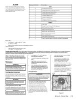
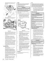
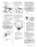
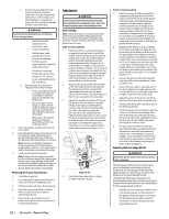
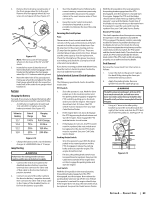
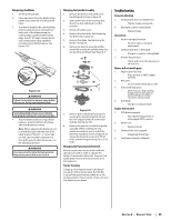
2. Remove the lock nut (a) securing one of the front gauge wheel (b) to the deck. Remove the front gauge wheel (b), hex screw (c) and spacer (d). See Figure 4-11. (b) (a) (d) (e) (c) Figure 4-11 Note: There are a pair of front gauge wheels on the nose of the 54" and 60" decks. 3. Insert the hex screw (c) into the one of three index holes in the front gauge wheel bracket (e) that will give the front gauge wheel (b) a 1⁄4-1⁄2" clearance with the ground. 4. Note the index hole of the just adjusted front auge wheel (b), and adjust the other front gauge wheel (b) into the respective index hole of the other front gauge wheel bracket (e). Service Charging the Battery Test and, if necessary, recharge the battery after the tractor has been stored for a period of time. • A voltmeter or load tester should read 12.6 volts (DC) or higher across the battery terminals. See Figure 4-12. Voltmeter Reading 12.7 12.4 12.2 12.0 State of Charge 100% 75% 50% 25% Charging Time Full Charge 90 Min. 180 Min. 280 Min. Figure 4-12 • Charge the battery with a 12-volt battery charger at a MAXIMUM rate of 10 amps. Jump Starting WARNING Failure to use this starting procedure can cause sparking, and the gases in the battery to explode. 1. Connect the end of one cable to the disabled machine battery's positive terminal; then connect the other end of that cable to the booster battery's positive terminal. 2. Connect one end of the other cable to the booster battery's negative terminal; then connect the other end of that cable to the frame of the disabled tractor, as far from the battery as possible. 3. Start the disabled tractor following the normal starting instructions previously provided; then disconnect the jumper cables in the exact reverse order of their connection. 4. Have the tractor's electrical system checked and repaired as soon as possible to eliminate the need for jump starting. Servicing Electrical System Fuse There are two fuses located inside the left console. Lift the seat and look down at the left console to find the location of the fuses. One 30 amp fuse for the power steering and one 25 amp fuse the ignition, PTO, etc. These are standard plug-in type automotive fuses. Always use the same capacity fuse for replacement. Check the 30 amp fuse if the power steering is not working and check the 25 amp fuse for all other electrical problems. If you have a recurring problem with blown fuses, have the tractor's electrical system checked by your Cub Cadet Service Dealer. Safety Interlock System & Switch Operation Checks The following operational checks should be made daily: PTO Switch 1. Sit in the operator's seat. With the drive pedals are in the neutral position and the parking brake engaged, engage the PTO switch by pulling up on the knob and try to start the engine. The engine should not start. If it does, the PTO switch must be replaced. See your Cub Cadet Service Dealer. 2. If the engine does not start, disengage the PTO by pressing the knob down and start the engine. Now engage the PTO and the blades should rotate. 3. If the blades do not turn, the PTO switch must be replaced, the seat switch must be replaced or the electric PTO clutch must be repaired. See your Cub Cadet Service Dealer. Parking Brake Switch • Sit in the operator's seat. With the drive pedals in the neutral position and the PTO disengaged, release the parking brake and try to start the engine. The engine should not start. • If it does, the parking brake switch must be repositioned or replaced. See your Cub Cadet Service Dealer. If the engine does not start, engage the parking brake and start the engine. Seat Switch With the drive pedals in the neutral position, the parking brake engaged and the PTO disengaged, start the engine. Now release the parking brake and raise up off the seat. Release the operator's seat and the engine should stop. If the engine does not stop, the seat switch must be replaced. See your Cub Cadet Service Dealer. With the drive pedals in the neutral position, the parking brake engaged and the PTO disengaged, sit in the operator's seat and start the engine. Engage the PTO and the blades should start to rotate. Raise up slightly off the operator's seat and the blades should stop. If the blades do not stop when you dismount from the operator's seat, the seat switch must be replaced. See your Cub Cadet Service Dealer. Electric PTO Clutch This clutch operates when the engine is running, the operator is in the operator's seat and the PTO is engaged. This electric clutch is a normally trouble free device. If a problem develops and the blades do not turn, first check the 25 amp fuse, then investigate the wiring harness and the connections to the seat switch, the PTO switch and the electric blade clutch. Then check the seat switch, the PTO switch and finally the electric blade clutch. If the PTO clutch is still not working properly, see an authorized service dealer. Deck Removal Remove the mower deck from the tractor as follows: 1. Lower the deck to the ground. Capture the deck lift by placing the clevis pin behind the lowest position. 2. Apply the parking brake. Remove ignition key and the spark plug cap. WARNING The muffler and any surrounding parts at the rear of the tractor may be extremely hot, and could cause serious burns. Use extreme caution when near the muffler. Allow the muffler to fully cool before removing the belt from the PTO pulley. 4. Using a 1⁄2" drive in the idler pulley bracket (a), turn the wrench towards the right of the tractor and slide the PTO belt (b) off the PTO pulley (c). See Figure 4-13. (c) (b) (a) Figure 4-13 Section 4 - Product Care 23
-
 1
1 -
2
-
3
-
4
-
5
-
6
-
7
-
8
-
9
-
10
-
11
-
12
-
13
-
14
-
15
-
16
-
17
-
 18
18 -
 19
19 -
 20
20 -
 21
21 -
 22
22 -
 23
23 -
 24
24 -
 25
25 -
 26
26 -
 27
27 -
 28
28 -
29
-
30
-
31
-
32
 |
 |
