Cub Cadet PRO Z 972S KW Operation Manual - Page 13
Arm Rest Height Knobs Not Shown
 |
View all Cub Cadet PRO Z 972S KW manuals
Add to My Manuals
Save this manual to your list of manuals |
Page 13 highlights
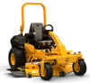
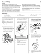
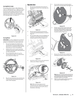
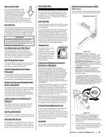
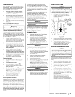
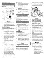
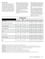
Reverse Drive Pedal The reverse drive pedal is located on the right side of the tractor, to the right of the forward drive pedal, along the running board. Ground speed is also controlled with the reverse drive pedal. The further downward the pedal is pivoted, the faster the tractor will travel. The pedal will return to its original/neutral position when it's not pressed. Fuel Tank Caps The fuel tank caps are located on the top of the fuel tank on the left and right side of the seat. Turn the fill cap counter-clockwise to remove and clockwise until it clicks three times to tighten. Always re-install the fuel cap tightly onto the fuel tank after removing. WARNING Never fill the fuel tank when the engine is running. If the engine is hot from recently running, allow to cool for several minutes before refueling. Highly flammable gasoline could splash onto the engine and cause a fire. Seat Adjustment Lever (Not Shown) The seat adjustment lever is located below the front/right of the seat. The lever allows for adjustment forward or rearward of the operator's seat. Refer to the Assembly & Set-Up section for instructions on adjusting the seat position. Seat Tilt Knob (Not Shown) The seat tilt knob is located on the left side of the seat. Refer to the Assembly & Set-Up section for instructions on adjusting the seat tilt. Arm Rest Height Knobs (Not Shown, If Equipped) The arm height knobs are located under the seat arms and can be used to adjust the height of the arm rests. Refer to the Assembly & Set-Up section for instructions on adjusting the arm rest position. Mechanical Suspension Mechanism (Not Shown, If Equipped) The mechanical suspension mechanism is located on the front of the seat and can adjust the weight/ ride adjustment for operators in the 125- to 275-pound weight range. Refer to the Assembly & Set-Up section for instructions on adjusting the mechanical suspension mechanism. Lumbar Support Lever (Not Shown, If Equipped) The lumbar support lever is located on the right side of the seat on the seat back. Refer to the Assembly & Set-Up section for instructions on adjusting the lumbar support. Seat Prop (Not Shown) The seat prop is located on the left, rear side of the operator's seat. It is used to prop the seat forward. Seat Latch (Not Shown) The seat latch is located below the rear, center of the operators seat. The latch is used to secure the seat into the operating position. Lift the latch and tilt the seat forward access the area under the seat. Deck Height Index 4.25" 3.25" 2.25" 1.25" 4.50" 3.50" 2.50" 1.50" 4.75" 3.75" 2.75" 1.75" 5" 4" 3" 2" 1" The deck height index consists of several holes located on the left of the foot platform. Each hole corresponds to a 1⁄4" change in the deck height position ranging from 1" at the lowest notch to 5" at the highest notch. Deck Lift Pedal The deck lift pedal is located on the left front corner of the foot platform, and is used to raise and lower the mowing deck. To raise the mowing deck to the transport position, push the pedal all the way forward until the deck transportation lock snaps into position. To remove the deck from the transport position push forward on the deck lift pedal and pull up on the deck lock rod. To position the deck push the pedal all the way forward, remove the clevis pin and reinsert it in the desired cutting height and slowly release pressure on the pedal until you reach the clevis pin. Transport Lock The transport lock is located on the left side of the operator's seat and is used to lock the deck in the transport position. Press down on the deck lift pedal and lift up on the deck lift release lever to release the deck. TRANSPORT FLOAT LOCK TRANSPORT Transmission Oil Expansion Reservoir (Not Shown, If Equipped) The 500 series is equipped with an integrated transmission oil expansion reservoir on both the LH and RH transmission assemblies. The 700 and 900 series are equipped with a transmission oil expansion reservoir located under the seat and it is connected by hoses to the RH and LH transmission assemblies. The function of the reservoir is to hold the natural expansion of transmission oil that occurs as the transmission warms up during operation. DO NOT FILL THE RESERVOIR. Under normal operating conditions, no oil should be added to the reservoir. The COLD oil level should be approximately 1⁄4" above the bottom of the reservoir on 700 and 900 models and 1/8" up the dipstick on 500 models. See the Product Care section of this manual for more information on the transmission oil expansion reservoirs. Note: Prior to the initial operation of the tractor, the oil level in the reservoir may be slightly higher than the maximum due to air in the oil lines. Operation of the tractor will eventually purge the air from the lines and the oil level will settle to the maximum. Steering Column Adjustment Lever The steering column adjustment lever is located on the right side of the steering column. To adjust the column pull up on the steering column adjustment lever (a) and move the steering column up into the desired position. Release the steering column adjustment lever (a) to secure the steering column in the desired position. Cup Holder The cup holder is located between the fuel tank and the control panel to the right of the seat. Roll Over Protective Structure (ROPS) ROPS Positions Refer to Figure 3-2 and the following descriptions and uses for the three (3) positions for the ROPS. Operation Position BaTgrgaenrsPpoosrittwiointh Transport Position Figure 3-2 • TRANSPORT: Only to be used when transporting the tractor or when they need to be momentarily folded-down to avoid contact with items such as tree limbs, clothes lines, guy wires, utility poles, buildings, etc. • TRANSPORT WITH BAGGER: Allows for the ROPS to be lowered for situations outlined for the TRANSPORT position when the tractor is equipped with a bagger. • OPERATION: The ROPS should always be in this position when operating unless the situations involved outlined in the TRANSPORT and TRANSPORT WITH BAGGER descriptions arise. 1. To change the position of the ROPS, pull slightly up/push forward on the upper ROPS to relieve any tension on the locking pin (a) and rotate the locking pin (a) from the LOCKED (b) position into the ADJUSTMENT (c) position. Repeat the procedure for the locking pin on the opposite side. See Figure 3-3. (c) (b) (a) Figure 3-3 2. Move the ROPS into the desired position. The three positions are TRANSPORT (a) position, TRANSPORT WITH BAGGER (b) position and into the OPERATION (c) position. See Figure 3-2. 3. Rotate both locking pins into the LOCKED position. Move the upper ROPS slightly until the locking pins are fully engaged in the LOCKED position. Section 3 - Controls & Operation 13
-
 1
1 -
2
-
3
-
4
-
5
-
6
-
7
-
 8
8 -
 9
9 -
 10
10 -
 11
11 -
 12
12 -
 13
13 -
 14
14 -
 15
15 -
 16
16 -
 17
17 -
 18
18 -
19
-
20
-
21
-
22
-
23
-
24
-
25
-
26
-
27
-
28
-
29
-
30
-
31
-
32
 |
 |