Cub Cadet PRO Z 972S KW Operation Manual - Page 9
Operator's Seat
 |
View all Cub Cadet PRO Z 972S KW manuals
Add to My Manuals
Save this manual to your list of manuals |
Page 9 highlights
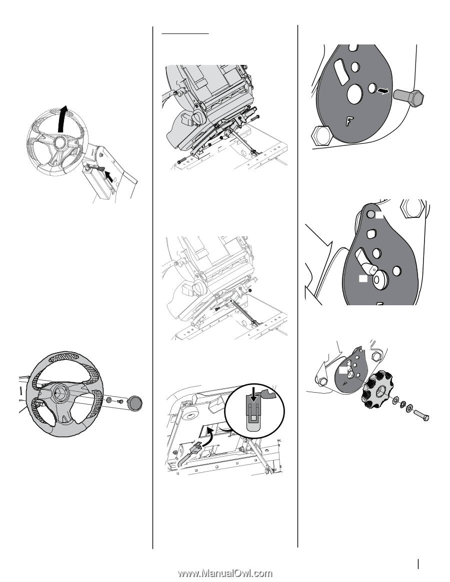
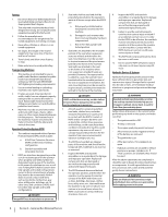
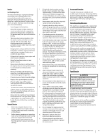
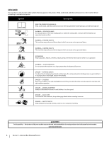
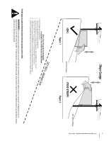
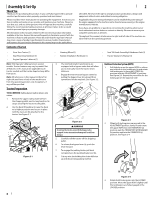
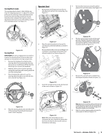
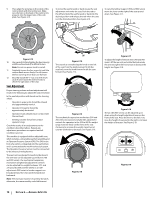
. Steering Wheel Column The steering wheel column is tilted all the way down for shipping purposes. To adjust the column pull up on the steering column adjustment lever (a) and move the steering column up into the desired position. Release the steering column adjustment lever (a) to secure the steering column in the desired position. See Figure 2-5. Operator's Seat 1. Remove the two flange lock nuts (b) and shoulder bolts (a) from the manual bag. See Figure 2-7. (a) 5. Remove the screw (a) securing the recliner plate in the seat back position. See Figure 2-10. (a) (a) Figure 2-5 Steering Wheel IMPORTANT! Do not use impact tools to install or remove the steering wheel. Doing so may cause damage to critical power steering components. 1. Remove the hardware for attaching the steering wheel from beneath the steering wheel cap (a). Carefully pry off the steering wheel cap (a) to remove the hardware. 2. With the wheels of the machine pointing straight forward, place the steering wheel (b) over the steering shaft. 3. Place the belleville washer (c) over the steering wheel (b) and secure with the hex lock screw (d). See Figure 2-6. (b) (c) (d) (a) Figure 2-6 4. Place the steering wheel cover over the center of the steering wheel and push downward until it "clicks" into place. (b) (b) (a) Figure 2-7 2. Place the seat into position and secure the seat into place with the hardware as shown in Figure 2-7. 3. Remove the shoulder screw (a) and flange lock nut (b) from manual bag and install the seat lockout bracket (c) as shown in Figure 2-8. (b) (a) (c) Figure 2-8 4. Insert the wiring harness (a) into the bottom of the seat as shown in Figure 2-9. (a) (a) Figure 2-9 Note: When the wiring harness (a) is connected, be sure to push the excess wire from the wire harness (a) into the seat box hole before continuing. Figure 2-10 6. Tilt the seat forward into the full forward position. Replace the recliner plate with the clinch-stud (a) and the recliner pin (b) passing through the recliner plate in the locations shown in Figure 2-11. (a) (b) Figure 2-11 7. Remove the seat tilt knob assembly from the bag and install as shown in Figure 2-12. (a) (h) (e) (f) (b) (d) (c) (g) Figure 2-12 Note: Be sure to orient the recliner plate (a) and install the plastic washer (b), spring washer (c) and metal washer (d) as shown in Figure 2-12. The plastic washer is on the inside . 8. Slide the recliner bearing plate (a) onto the recliner pin (e). Refer to Figure 2-12. Section 2 - Assembly & Set-Up 9
-
 1
1 -
2
-
3
-
 4
4 -
 5
5 -
 6
6 -
 7
7 -
 8
8 -
 9
9 -
 10
10 -
 11
11 -
 12
12 -
 13
13 -
 14
14 -
15
-
16
-
17
-
18
-
19
-
20
-
21
-
22
-
23
-
24
-
25
-
26
-
27
-
28
-
29
-
30
-
31
-
32
 |
 |