D-Link DGS-1224T Product Manual - Page 13
Rear Panel, DGS-1224TP, Front Panel, Port LED 1-20, 21T~24T
 |
UPC - 790069264467
View all D-Link DGS-1224T manuals
Add to My Manuals
Save this manual to your list of manuals |
Page 13 highlights
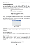
3 Product Introduction Rear Panel D-Link Web Smart Switch User Manual Figure 11 - DGS-1224T Rear Panel Reset: By pressing the Reset button the Switch will change back to the default configuration and all changes will be lost. Power: The power port is where to connect the AC power cord. DGS-1224TP 24 Port 10/100/1000BaseT PoE with 4 Combo SFP Smart Switch Front Panel Figure 12 - DGS-1224TP Front Panel Power LED: The Power LED flashes when the Switch is connected to a power source. Power Max LED: The Power Max lights up when the system power resource remain ≦15.4W, in the meantime, system will not provide power to the additional PoE PD inserted. CPU LED: When the CPU LED is blinking, then the switch is in the normal condition. If the CPU LED is off or stays in solid light state that means the system might have crashed or firmware upgrade has failed. Fan Error LED: The FAN LED shows the status of the fans, light off indicates all fans work fine and the red light indicates that one or multiple fans are working abnormally. Mode Button: To select the mode of port LED, the Link/Act and PoE LED under the mode button will solid green to indicate which mode is selected. Port LED (1-20, 21T~24T): The port LED will indicate Link/Act or PoE status of this port depending on the LED mode you selected: Mode Color Status Link/Act Off The corresponding port is link down Solid Green The corresponding port is link up at 1000Mbps Blinking Green Data is sending or receiving on corresponding port at 1000Mbps Solid Orange The corresponding port is link up at 10Mbps or 100Mbps Blinking Orange Data is sending or receiving on corresponding port at 10Mbps or 100Mbps PoE Off No power feeding or no PD found on corresponding port Solid Green The corresponding port is providing standard 48V power to the PD Solid Orange PoE error has occurred at this port. You may check the detailed information for the errors on the PoE Port Setting page in Web-based Management Utility. Port LED (21F~24F): The port LED will indicate Link/Act of this port: Mode Color Status Link/Act Off The corresponding port is link down Solid Green The corresponding port is link up at 1000Mbps 9
-
 1
1 -
2
-
3
-
4
-
5
-
6
-
7
-
 8
8 -
 9
9 -
 10
10 -
 11
11 -
 12
12 -
 13
13 -
 14
14 -
 15
15 -
 16
16 -
 17
17 -
 18
18 -
19
-
20
-
21
-
22
-
23
-
24
-
25
-
26
-
27
-
28
-
29
-
30
-
31
-
32
-
33
-
34
-
35
-
36
-
37
-
38
-
39
-
40
-
41
-
42
-
43
-
44
-
45
-
46
-
47
-
48
-
49
-
50
-
51
-
52
 |
 |
