D-Link DGS-1224T Product Manual - Page 8
Getting Started, Management Options, Using Web-based Management Utility, Supported Web Browsers
 |
UPC - 790069264467
View all D-Link DGS-1224T manuals
Add to My Manuals
Save this manual to your list of manuals |
Page 8 highlights
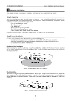
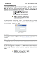
2 Getting Started D-Link Web Smart Switch User Manual 2 Getting Started This chapter guides you how to get into and introduces the management interface of D-Link Web-Smart Switch. Management Options The D-Link Web Smart Switch can be managed through any port on the device by using the Web-based Management Utility or through any PC using the SmartConsole Utility. If you want to manage only one D-Link Web Smart Switch, the Web-Based Management Utility is the better option. Each switch must be assigned its own IP Address, which is used for communication with Web-Based Management Utility or an SNMP network manager and the PC should have an IP address in the same range as the switch. However, if you want to manage multiple D-Link Web Smart Switches, the SmartConsole Utility is the better option. Using the SmartConsole Utility, you don't need to change the IP address of your PC and it is easy to start the initial setting of multiple Smart Switches. Please refer to the following detailed installation instructions for the Web-Based Management Utility and the SmartConsole Utility. Using Web-based Management Utility After a successful physical installation, you can configure the Switch, monitor the LED panel, and display statistics graphically using a web browser. Supported Web Browsers The embedded Web-based Management Utility currently supports the following web browsers: Microsoft Internet Explorer ver. 6.0, 5.5 Mozilla ver. 1.7.12, 1.6 Firefox ver. 1.5, 1.0.7 Netscape ver. 8.0.4, 7.2 Opera ver. 8.5, 7.6 Safari ver. 2.0.2 Connecting to the Switch You need the following equipment to begin the web configuration of your device: 1. A PC with a RJ-45 Ethernet connection 2. A standard Ethernet cable Connect the Ethernet cable to any of the ports on the front panel of the switch and to the Ethernet port on the PC. Figure 5 -Connected Ethernet cable 4
-
 1
1 -
2
-
 3
3 -
 4
4 -
 5
5 -
 6
6 -
 7
7 -
 8
8 -
 9
9 -
 10
10 -
 11
11 -
 12
12 -
 13
13 -
14
-
15
-
16
-
17
-
18
-
19
-
20
-
21
-
22
-
23
-
24
-
25
-
26
-
27
-
28
-
29
-
30
-
31
-
32
-
33
-
34
-
35
-
36
-
37
-
38
-
39
-
40
-
41
-
42
-
43
-
44
-
45
-
46
-
47
-
48
-
49
-
50
-
51
-
52
 |
 |
