D-Link DGS-1250 Quick Install Guide - Page 10
Rear Panel Components, RJ45 Ports, SFP/SFP+ Ports, DGS-1250-28X, LED Indicators - d link 52x
 |
View all D-Link DGS-1250 manuals
Add to My Manuals
Save this manual to your list of manuals |
Page 10 highlights
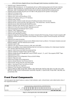
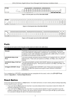
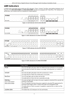
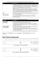
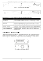
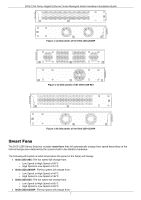
DGS-1250 Series Gigabit Ethernet Smart Managed Switch Hardware Installation Guide LED PoE DGS-1250-28XMP DGS-1250-52XMP Description RJ45 Ports: This LED will light solid green when there is a connection (or link) to a 1000 Mbps Ethernet device or solid amber when there is a connection (or link) to a 10/100 Mbps Ethernet device on any of the RJ45 ports. The LED will blink green when a 1000 Mbps port is active or blink amber when a 10/100 Mbps port is active. The LED will be off when there is no link or activity. SFP/SFP+ Ports: This LED will light solid green when there is a connection (or link) to a 10 Gbps Ethernet device or solid amber when there is a connection (or link) to a 1 Gbps Ethernet device at any at any of the SFP/SFP+ ports. The LED will blink green when a 10 Gbps port is active or blink amber when a 1 Gbps port is active. The LED will be off when there is no link or activity. This LED will light solid green when the corresponding ports are feeding power to the PoE devices plugged in. This LED will light solid amber when the port is in an error condition state. This LED will be off when the ports are not supplying power to the devices plugged into the ports. The following table describes the behavior of the LEDs during the bootup process: Switch(es) Description DGS-1250-28X DGS-1250-52X The power LED blinks green when the switch is powered on and will continue to blink during the bootup process until the system is ready. The Link/Act port LEDs light solid green/amber when the switch is powered on. The green LEDs will then blink until the system is ready. The amber LEDs will be off until the system is ready. DGS-1250-28XMP DGS-1250-52XMP The power LED blinks green when the switch is powered on and will continue to blink during the bootup process until the system is ready. The Link/Act port LEDs light solid green/amber when the switch is powered on. The green LEDs will then blink until the system is ready. The amber LEDs will be off until the system is ready. The Link/Act mode LED lights solid green during and after the bootup process. Please refer to the "LED Indicators" section in the Appendix A - Technical Specifications for more LED information. Rear Panel Components The rear panel of this switch features a security lock, a GND, an AC power connector, and a power cord retainer hole. Figure 1-9 Rear panel view of the DGS-1250-28X Figure 1-10 Rear panel view of the DGS-1250-28XMP 5
-
 1
1 -
2
-
3
-
4
-
 5
5 -
 6
6 -
 7
7 -
 8
8 -
 9
9 -
 10
10 -
 11
11 -
 12
12 -
 13
13 -
 14
14 -
 15
15 -
16
-
17
-
18
-
19
-
20
-
21
-
22
-
23
-
24
-
25
-
26
-
27
-
28
-
29
-
30
-
31
-
32
-
33
-
34
-
35
-
36
-
37
-
38
-
39
-
40
-
41
-
42
-
43
-
44
-
45
 |
 |
