D-Link DGS-1250 Quick Install Guide - Page 9
LED Indicators, DGS-1250-28XMP, Power, Console, Fan Error, PWR Max., Link/Act LEDs - d link 28xmp
 |
View all D-Link DGS-1250 manuals
Add to My Manuals
Save this manual to your list of manuals |
Page 9 highlights
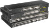
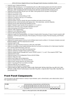
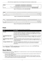
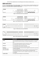
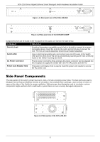
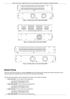
DGS-1250 Series Gigabit Ethernet Smart Managed Switch Hardware Installation Guide LED Indicators Located on the front panel of this switch are LED indicators: Power, Console, Fan Error, and Link/Act indicators for all the ports. The DGS-1250-28XMP and DGS-1250-52XMP switches are equipped with Power Max., PoE indicators for all the ports, and Link/Act and PoE indicators for mode selection. Figure 1-5 LED indicators for the DGS-1250-28X Figure 1-6 LED indicators for the DGS-1250-28XMP Figure 1-7 LED indicators for the DGS-1250-52X LED Power Console Fan Error PWR Max. DGS-1250-28XMP DGS-1250-52XMP Link/Act LEDs Figure 1-8 LED indicators for the DGS-1250-52XMP Description This LED will light solid green after the Switch has been powered on successfully. This LED will be off when the Switch is no longer receiving power (i.e. powered off). This LED will light solid green when the console port is active. This LED will be off when the console port is not active. This LED will light solid red when the fan fails. This LED will be off when the fan is operating normally. This LED will light solid red when the power supplied to attached PDs exceeds the maximum PoE budget. This LED will blink red when the power supplied to attached PDs approaches the maximum PoE budget (within 7 Watts) and enters the Guardband mode. This LED will be off when no power is supplied to attached PDs or when no PDs are attached. The Switch has LED indicators for Link and Activity. 4
-
 1
1 -
2
-
3
-
 4
4 -
 5
5 -
 6
6 -
 7
7 -
 8
8 -
 9
9 -
 10
10 -
 11
11 -
 12
12 -
 13
13 -
 14
14 -
15
-
16
-
17
-
18
-
19
-
20
-
21
-
22
-
23
-
24
-
25
-
26
-
27
-
28
-
29
-
30
-
31
-
32
-
33
-
34
-
35
-
36
-
37
-
38
-
39
-
40
-
41
-
42
-
43
-
44
-
45
 |
 |
