D-Link DGS-1250 Quick Install Guide - Page 16
SFP+/SFP Ports, Appendix A, Technical Specifications, FCC 21 CFR
 |
View all D-Link DGS-1250 manuals
Add to My Manuals
Save this manual to your list of manuals |
Page 16 highlights
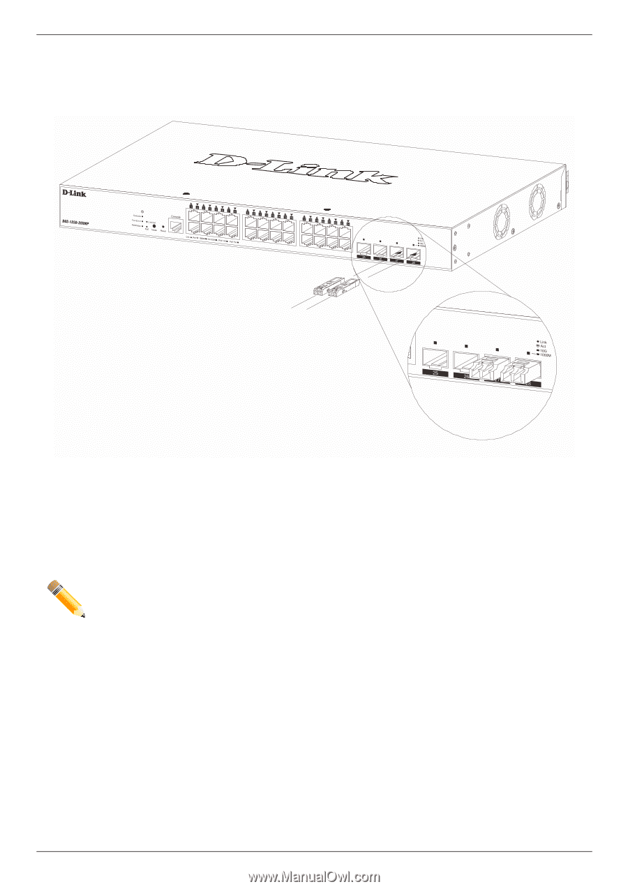
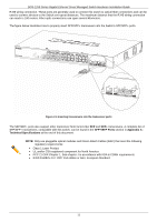
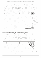
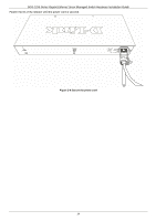
DGS-1250 Series Gigabit Ethernet Smart Managed Switch Hardware Installation Guide RJ45 wiring connection. These ports are generally used to connect this switch to optical fiber connections and can be used to connect devices to the Switch over great distances. The maximum distance that the RJ45 wiring connection can reach is 100 meters. Fiber optic connections can span several kilometers. The figure below illustrates how to properly insert SFP/SFP+ transceivers into the Switch's SFP/SFP+ ports. Figure 2-4 Inserting transceivers into the transceiver ports The SFP/SFP+ ports also support other transceiver form factors like SFP and SFP+ transceivers. A complete list of SFP/SFP+ transceivers, compatible with this switch, can be found in the SFP+/SFP Ports section in Appendix A Technical Specifications at the end of this document. NOTE: Only use pluggable optical modules and Direct-Attach Cables (DAC) that meet the following regulatory requirements: Class 1 Laser Product UL and/or CSA registered component for North America FCC 21 CFR Chapter 1, Sub-chapter J in accordance with FDA & CDRH requirements IEC/EN 60825-1/-2: 2007 2nd edition or later, European Standard 11
-
 1
1 -
2
-
3
-
4
-
5
-
6
-
7
-
8
-
9
-
10
-
 11
11 -
 12
12 -
 13
13 -
 14
14 -
 15
15 -
 16
16 -
 17
17 -
 18
18 -
 19
19 -
 20
20 -
 21
21 -
22
-
23
-
24
-
25
-
26
-
27
-
28
-
29
-
30
-
31
-
32
-
33
-
34
-
35
-
36
-
37
-
38
-
39
-
40
-
41
-
42
-
43
-
44
-
45
 |
 |