D-Link DGS-1250 Quick Install Guide - Page 11
Side Panel Components, Security Lock, Switch GND, AC Power Connector, Power Cord Retainer Hole
 |
View all D-Link DGS-1250 manuals
Add to My Manuals
Save this manual to your list of manuals |
Page 11 highlights
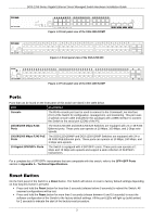
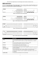
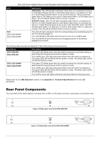
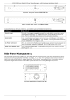
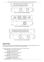
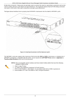
DGS-1250 Series Gigabit Ethernet Smart Managed Switch Hardware Installation Guide Figure 1-11 Rear panel view of the DGS-1250-52X Figure 1-12 Rear panel view of the DGS-1250-52XMP Components that can be found on the rear panel of this switch are listed in the table below. Component Description Security Lock Provide a Kensington-compatible security lock to be able to connect to a secure immovable device. Insert the lock into the notch and turn the key to secure the lock. The lock-and-cable apparatus should be purchased separately. Switch GND Use an electrical grounding wire and connect one end of the wire to the Switch GND and the other end of the wire to an electrical grounding point most commonly found on the Switch mounting rack itself. AC Power Connector The AC power cord with a three-pronged AC power connector can be plugged into this receptacle to supply the Switch with 100-240 VAC power at 50-60 Hz. Power Cord Retainer Hole The power cord retainer hole is used to insert the power cord retainer to secure the AC power cord. Side Panel Components The side panels of this switch contain heat vents, fans, and rack-mounting screw holes. The heat vents are used to dissipate internal heat and facilitate internal air circulation. Do not block these openings. Leave at least 4 inches of space at the sides of the Switch for proper ventilation. Without proper heat dissipation and air circulation, system components might overheat which could lead to system failure or even severely damaged components. Figure 1-13 Side panels of the DGS-1250-28X 6
-
 1
1 -
2
-
3
-
4
-
5
-
 6
6 -
 7
7 -
 8
8 -
 9
9 -
 10
10 -
 11
11 -
 12
12 -
 13
13 -
 14
14 -
 15
15 -
 16
16 -
17
-
18
-
19
-
20
-
21
-
22
-
23
-
24
-
25
-
26
-
27
-
28
-
29
-
30
-
31
-
32
-
33
-
34
-
35
-
36
-
37
-
38
-
39
-
40
-
41
-
42
-
43
-
44
-
45
 |
 |
