D-Link DGS-3620-28SC-EI Hardware Installation Guide - Page 20
Rear Panel Description
 |
View all D-Link DGS-3620-28SC-EI manuals
Add to My Manuals
Save this manual to your list of manuals |
Page 20 highlights
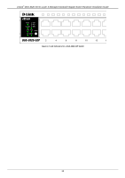
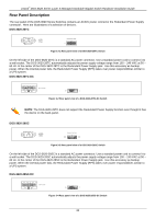
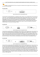
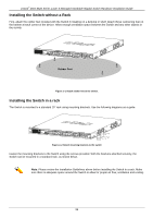
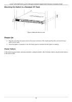
xStack® DGS-3620 Series Layer 3 Managed Stackable Gigabit Switch Hardware Installation Guide Rear Panel Description The rear panel of the DGS-3620 Series Switches contains an AC/DC power connector the Redundant Power Supply connector. Here are illustrations of a selection of devices. DGS-3620-28TC Figure 3-1 Rear panel view of a DGS-3620-28TC Switch On the left side of the DGS-3620-28TC is a standard AC power connector. Use a standard power cord to connect it to a wall socket. The DGS-3620-28TC automatically adjusts the power supply voltage range from 100 ~ 240 VAC at 50 ~ 60 Hz. In the center of the DGS-3620-28TC is the Redundant Power Supply jack. Use this accessory as backup power. When the internal power fails, the Redundant Power Supply (RPS) takes over power responsibilities similar to a UPS system. DGS-3620-28TC-DC Figure 3-2 Rear panel view of a DGS-3620-28TC-DC Switch NOTE: The DGS-3620-28TC does not support the Redundant Power Supply function even thought it has the device on the back-panel. DGS-3620-28SC Figure 3-3 Rear panel view of a DGS-3620-28SC Switch On the left side of the DGS-3620-28SC is a standard AC power connector. Use a standard power cord to connect it to a wall socket. The DGS-3620-28SC automatically adjusts the power supply voltage range from 100 ~ 240 VAC at 50 ~ 60 Hz. In the center of the DGS-3620-28SC is the Redundant Power Supply jack. Use this accessory as backup power. When the internal power fails, the Redundant Power Supply (RPS) takes over power responsibilities similar to a UPS system. DGS-3620-28SC-DC Figure 3-4 Rear panel view of a DGS-3620-28SC-DC Switch 20
-
 1
1 -
2
-
3
-
4
-
5
-
6
-
7
-
8
-
9
-
10
-
11
-
12
-
13
-
14
-
 15
15 -
 16
16 -
 17
17 -
 18
18 -
 19
19 -
 20
20 -
 21
21 -
 22
22 -
 23
23 -
 24
24 -
 25
25 -
26
-
27
-
28
-
29
-
30
-
31
-
32
-
33
-
34
-
35
-
36
-
37
-
38
-
39
-
40
-
41
-
42
-
43
-
44
-
45
-
46
-
47
-
48
-
49
-
50
-
51
-
52
-
53
-
54
-
55
-
56
-
57
-
58
-
59
-
60
-
61
-
62
-
63
-
64
-
65
-
66
-
67
-
68
 |
 |
