D-Link DGS-3620-28SC-EI Hardware Installation Guide - Page 25
Power
 |
View all D-Link DGS-3620-28SC-EI manuals
Add to My Manuals
Save this manual to your list of manuals |
Page 25 highlights
xStack® DGS-3620 Series Layer 3 Managed Stackable Gigabit Switch Hardware Installation Guide Mounting the Switch in a Standard 19" Rack Figure 2-3 Mount the switch in a rack Power On 1. Plug one end of the AC power cord into the power connector of the Switch and the other end into the local power source outlet. 2. Once the system is powered on, the LED's blink green to indicate that the system is resetting. Power Failure In the event of a power failure, just as a precaution, unplug the Switch. After the power returns, plug the switch back in to the power socket. 25
-
 1
1 -
2
-
3
-
4
-
5
-
6
-
7
-
8
-
9
-
10
-
11
-
12
-
13
-
14
-
15
-
16
-
17
-
18
-
19
-
 20
20 -
 21
21 -
 22
22 -
 23
23 -
 24
24 -
 25
25 -
 26
26 -
 27
27 -
 28
28 -
 29
29 -
 30
30 -
31
-
32
-
33
-
34
-
35
-
36
-
37
-
38
-
39
-
40
-
41
-
42
-
43
-
44
-
45
-
46
-
47
-
48
-
49
-
50
-
51
-
52
-
53
-
54
-
55
-
56
-
57
-
58
-
59
-
60
-
61
-
62
-
63
-
64
-
65
-
66
-
67
-
68
 |
 |

xStack
®
DGS-3620 Series Layer 3 Managed Stackable Gigabit Switch Hardware Installation Guide
25
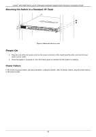
Mounting the Switch in a Standard 19" Rack
Figure 2
–
3 Mount the switch in a rack
Power On
1.
Plug one end of the AC power cord into the power connector of the Switch and the other end into the local
power source outlet.
2.
Once the system is powered on, the LED’s blink
green to indicate that the system is resetting.
Power Failure
In the event of a power failure, just as a precaution, unplug the Switch. After the power returns, plug the switch back in
to the power socket.