D-Link DGS-3620-28SC-EI Hardware Installation Guide - Page 21
DGS-3620-28PC, DGS-3620-52T, DGS-3620-52P
 |
View all D-Link DGS-3620-28SC-EI manuals
Add to My Manuals
Save this manual to your list of manuals |
Page 21 highlights
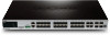
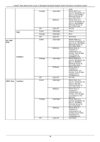
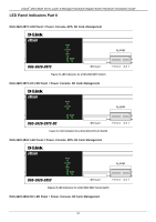
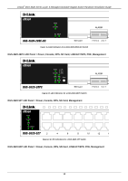
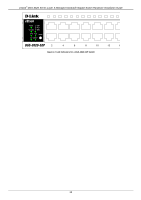
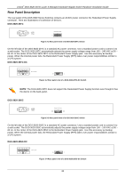
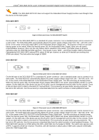
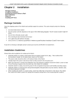
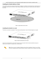
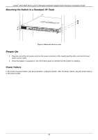
xStack® DGS-3620 Series Layer 3 Managed Stackable Gigabit Switch Hardware Installation Guide NOTE: The DGS-3620-28TC-DC does not support the Redundant Power Supply function even though it has the device on the back-panel. DGS-3620-28PC Figure 3-5 Rear panel view of a DGS-3620-28PC Switch On the left side of the DGS-3620-28PC is a standard AC power connector. Use a standard power cord to connect it to a wall socket. The DGS-3620-28PC automatically adjusts the power supply voltage range from 100 ~ 240 VAC at 50 ~ 60 Hz. In the center of the DGS-3620-28PC is the Redundant Power Supply jack. The purpose of PoE is to provide backup power to the switch. When the internal power fail, the Redundant Power Supply, takes over the power responsibilities. However, this is not the only feature that is valuable to this switch. It provides power to all ports operating under the POE 802.3af 30W spectrum. That means it uses 720W - and Power budget 740W at full power. Operating the DGS-3620-28PC without RPS, yields 15.4W per channel, so when all 24 devices are working only 370W are utilized. This falls within the budget of 390W. DGS-3620-52T Figure 3-6 Rear panel view of a DGS-3620-52T Switch On the left side of the DGS-3620-52T is a standard AC power connector. Use a standard power cord to connect it to a wall socket. The DGS-3620-52T automatically adjusts the power supply voltage range from 100 ~ 240 VAC at 50 ~ 60 Hz. In the center of the DGS-3620-52T is the Redundant Power Supply jack. Use this accessory as backup power. When the internal power fails, the Redundant Power Supply (RPS) takes over power responsibilities similar to a UPS system. On the right side of the device are two RJ-45 ports, one for management and the other for the console. There is also an alarm port to attach a General I/O Terminal block. This accessory can give better security protection. The last slot is SD card slot. Use this accessory to download data from the switch console or install updated firmware. DGS-3620-52P Figure 3-7 Rear panel view of a DGS-3620-52P Switch On the left side of the DGS-3620-52P is a standard AC power connector. Use a standard power cord to connect it to a wall socket. The DGS-3620-52P automatically adjusts the power supply voltage range from 100 ~ 240 VAC at 50 ~ 60 Hz. In the center of the DGS-3620-52P is the Redundant Power Supply jack. Use this accessory as backup power. When the internal power fails, the Redundant Power Supply (RPS) takes over power responsibilities similar to a UPS system. On the right side of the device are two RJ-45 ports, one for management and the other for the console. There is also an alarm port to attach a General I/O Terminal block. This accessory can give better security protection. The last slot is SD card slot. Use this accessory to download data from the switch console or install updated firmware. The DGS-3620-52P operates at 370W without the RPS, which falls into the budget of 390W. The switch also operates with a RPS. It supports 15.4W per channel. Therefore, with 48 channels it utilizes about 740W and is placed comfortably within the 760W budget limit. 21
-
 1
1 -
2
-
3
-
4
-
5
-
6
-
7
-
8
-
9
-
10
-
11
-
12
-
13
-
14
-
15
-
 16
16 -
 17
17 -
 18
18 -
 19
19 -
 20
20 -
 21
21 -
 22
22 -
 23
23 -
 24
24 -
 25
25 -
 26
26 -
27
-
28
-
29
-
30
-
31
-
32
-
33
-
34
-
35
-
36
-
37
-
38
-
39
-
40
-
41
-
42
-
43
-
44
-
45
-
46
-
47
-
48
-
49
-
50
-
51
-
52
-
53
-
54
-
55
-
56
-
57
-
58
-
59
-
60
-
61
-
62
-
63
-
64
-
65
-
66
-
67
-
68
 |
 |