Dell 700m Owner's Manual - Page 20
Bottom View, Stores software and data. - mini
 |
UPC - 302465977577
View all Dell 700m manuals
Add to My Manuals
Save this manual to your list of manuals |
Page 20 highlights
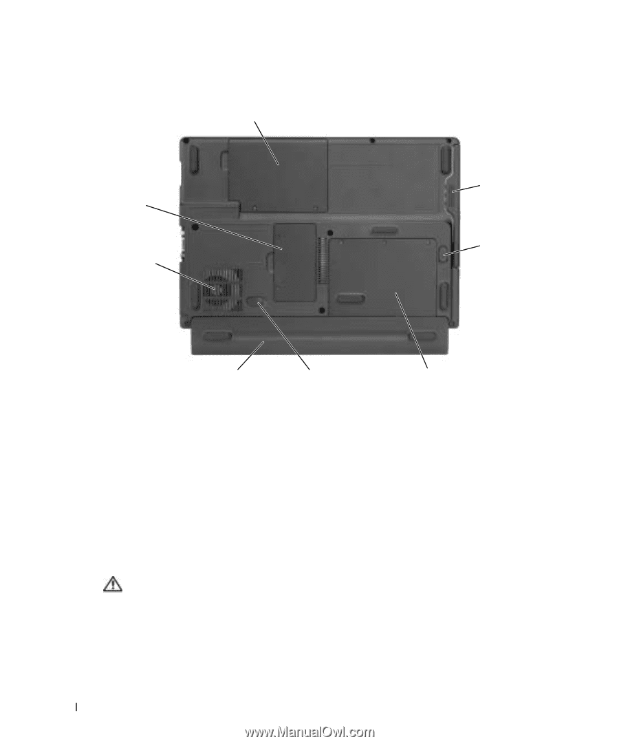
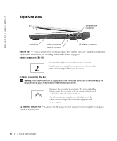
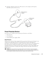
www.dell.com | support.dell.com Bottom View Mini PCI card and modem cover memory module cover air vent module bay module bay latch release battery* battery latch release hard drive cover *optional 8-cell battery is shown M O D U L E B A Y - You can install devices such as an optical drive in the module bay. For more information, see "Installing Module Bay Devices" on page 29. M O D U L E B A Y L A T C H R E L E A S E - Releases a device. See "Installing Module Bay Devices" on page 29 for instructions. HARD DRIVE - Stores software and data. B A T T E R Y L A T C H R E L E A S E - Releases a device. See "Using a Battery" on page 25 for instructions. B A T T E R Y / B A T T E R Y B A Y - When a battery is installed, you can use the computer without connecting the computer to an electrical outlet. See "Using a Battery" on page 25. A I R V E N T - The computer uses an internal fan to create airflow through the vents, which prevents the computer from overheating. CAUTION: Do not block, push objects into, or allow dust to accumulate in the air vents. Do not store your computer in a low-airflow environment, such as a closed briefcase, while it is running. Restricting the airflow can damage the computer or cause a fire. M E M O R Y M O D U L E C O V E R - Covers the compartment that contains the memory module. See "Memory" on page 73. M I N I P C I C A R D A N D M O D E M C O V E R - Covers the compartment that contains the Mini PCI card and modem. See "Mini PCI Card" on page 76 and "Modem" on page 75. 20 A Tour of Your Computer
-
 1
1 -
2
-
3
-
4
-
5
-
6
-
7
-
8
-
9
-
10
-
11
-
12
-
13
-
14
-
 15
15 -
 16
16 -
 17
17 -
 18
18 -
 19
19 -
 20
20 -
 21
21 -
 22
22 -
 23
23 -
 24
24 -
 25
25 -
26
-
27
-
28
-
29
-
30
-
31
-
32
-
33
-
34
-
35
-
36
-
37
-
38
-
39
-
40
-
41
-
42
-
43
-
44
-
45
-
46
-
47
-
48
-
49
-
50
-
51
-
52
-
53
-
54
-
55
-
56
-
57
-
58
-
59
-
60
-
61
-
62
-
63
-
64
-
65
-
66
-
67
-
68
-
69
-
70
-
71
-
72
-
73
-
74
-
75
-
76
-
77
-
78
-
79
-
80
-
81
-
82
-
83
-
84
-
85
-
86
-
87
-
88
-
89
-
90
-
91
-
92
-
93
-
94
-
95
-
96
-
97
-
98
-
99
-
100
-
101
-
102
-
103
-
104
-
105
-
106
-
107
-
108
-
109
-
110
-
111
-
112
-
113
-
114
 |
 |