Dell Alienware Aurora R12 Service Manual - Page 35
About this task, Steps
 |
View all Dell Alienware Aurora R12 manuals
Add to My Manuals
Save this manual to your list of manuals |
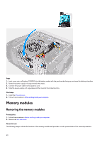
Page 35 highlights
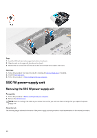
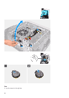
NOTE: Note the routing of all cables as you remove them so that you can route them correctly after you replace the powersupply unit. About this task The following images indicate the location of the power-supply unit and provides a visual representation of the removal procedure. Steps 1. Remove the two screws (#6-32) that secure the power-supply unit bracket to the power-supply unit cage. 2. Lift the power-supply unit bracket off the power-supply unit cage. 3. Slide the power-supply unit cage release latches to the unlock position. 4. Lift the power-supply unit cage and rotate the power-supply unit cage away from the chassis. 5. Press the releasing clip on the power-cable connectors and disconnect all the power cables from the power-supply unit. 6. Remove the four screws (#6-32) that secure the power-supply unit to the chassis. 7. Slide and lift the power-supply unit, along with the cables, off the chassis. 35
-
 1
1 -
2
-
3
-
4
-
5
-
6
-
7
-
8
-
9
-
10
-
11
-
12
-
13
-
14
-
15
-
16
-
17
-
18
-
19
-
20
-
21
-
22
-
23
-
24
-
25
-
26
-
27
-
28
-
29
-
 30
30 -
 31
31 -
 32
32 -
 33
33 -
 34
34 -
 35
35 -
 36
36 -
 37
37 -
 38
38 -
 39
39 -
 40
40 -
41
-
42
-
43
-
44
-
45
-
46
-
47
-
48
-
49
-
50
-
51
-
52
-
53
-
54
-
55
-
56
-
57
-
58
-
59
-
60
-
61
-
62
-
63
-
64
-
65
-
66
-
67
-
68
-
69
-
70
-
71
-
72
-
73
-
74
-
75
-
76
-
77
-
78
-
79
-
80
-
81
-
82
-
83
-
84
-
85
-
86
-
87
-
88
-
89
-
90
-
91
-
92
-
93
-
94
-
95
-
96
-
97
-
98
-
99
-
100
-
101
-
102
-
103
-
104
 |
 |
