Dell Alienware Aurora R12 Service Manual - Page 43
Table 2. Memory configuration matrix, Steps, CAUTION: To prevent damage to the memory module
 |
View all Dell Alienware Aurora R12 manuals
Add to My Manuals
Save this manual to your list of manuals |
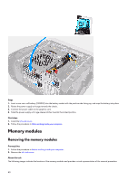
Page 43 highlights
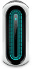
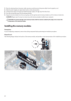
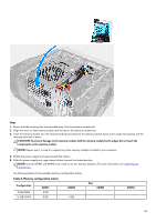
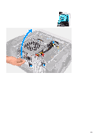
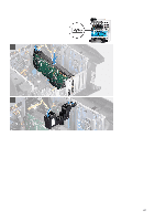
Steps 1. Ensure that the securing clips are extended away from the memory-module slot. 2. Align the notch on the memory module with the tab on the memory-module slot. 3. Insert the memory module into the memory-module slot and press the memory module down until it snaps into position and the securing clips lock in place. CAUTION: To prevent damage to the memory module, hold the memory module by the edges. Do not touch the components on the memory module. NOTE: Repeat step 1 to step 3 to replace any other memory modules installed in your computer. 4. Rotate the power-supply unit cage towards the chassis. 5. Slide the power-supply unit cage release latches towards the locked position. NOTE: Use slots XMM1 and XMM2 if you need to use two memory modules. For more information, see system-board components. The following table lists the available memory configuration matrix: Table 2. Memory configuration matrix Configuration 8 GB DDR4 16 GB DDR4 XMM1 8 GB 8 GB XMM2 8 GB Slot XMM3 XMM4 43
-
 1
1 -
2
-
3
-
4
-
5
-
6
-
7
-
8
-
9
-
10
-
11
-
12
-
13
-
14
-
15
-
16
-
17
-
18
-
19
-
20
-
21
-
22
-
23
-
24
-
25
-
26
-
27
-
28
-
29
-
30
-
31
-
32
-
33
-
34
-
35
-
36
-
37
-
 38
38 -
 39
39 -
 40
40 -
 41
41 -
 42
42 -
 43
43 -
 44
44 -
 45
45 -
 46
46 -
 47
47 -
 48
48 -
49
-
50
-
51
-
52
-
53
-
54
-
55
-
56
-
57
-
58
-
59
-
60
-
61
-
62
-
63
-
64
-
65
-
66
-
67
-
68
-
69
-
70
-
71
-
72
-
73
-
74
-
75
-
76
-
77
-
78
-
79
-
80
-
81
-
82
-
83
-
84
-
85
-
86
-
87
-
88
-
89
-
90
-
91
-
92
-
93
-
94
-
95
-
96
-
97
-
98
-
99
-
100
-
101
-
102
-
103
-
104
 |
 |