Dell Alienware Aurora R12 Service Manual - Page 62
Processor fan and heat-sink assembly
 |
View all Dell Alienware Aurora R12 manuals
Add to My Manuals
Save this manual to your list of manuals |
Page 62 highlights
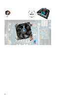
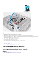
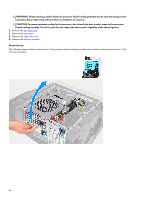
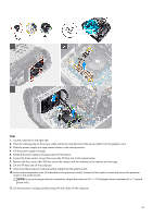
Processor fan and heat-sink assembly Removing the processor fan and heat-sink assembly Prerequisites 1. Follow the procedure in Before working inside your computer. NOTE: The heat sink may become hot during normal operation. Allow sufficient time for the heat sink to cool before you touch it. CAUTION: For maximum cooling of the processor, do not touch the heat transfer areas on the heat sink. The oils in your skin can reduce the heat transfer capability of the thermal grease. 2. Remove the left-side cover. About this task The following images indicate the location of the processor fan and heat-sink assembly and provides a visual representation of the removal procedure. 62
-
 1
1 -
2
-
3
-
4
-
5
-
6
-
7
-
8
-
9
-
10
-
11
-
12
-
13
-
14
-
15
-
16
-
17
-
18
-
19
-
20
-
21
-
22
-
23
-
24
-
25
-
26
-
27
-
28
-
29
-
30
-
31
-
32
-
33
-
34
-
35
-
36
-
37
-
38
-
39
-
40
-
41
-
42
-
43
-
44
-
45
-
46
-
47
-
48
-
49
-
50
-
51
-
52
-
53
-
54
-
55
-
56
-
 57
57 -
 58
58 -
 59
59 -
 60
60 -
 61
61 -
 62
62 -
 63
63 -
 64
64 -
 65
65 -
 66
66 -
 67
67 -
68
-
69
-
70
-
71
-
72
-
73
-
74
-
75
-
76
-
77
-
78
-
79
-
80
-
81
-
82
-
83
-
84
-
85
-
86
-
87
-
88
-
89
-
90
-
91
-
92
-
93
-
94
-
95
-
96
-
97
-
98
-
99
-
100
-
101
-
102
-
103
-
104
 |
 |

Processor fan and heat-sink assembly
Removing the processor fan and heat-sink assembly
Prerequisites
1.
Follow the procedure in
Before working inside your computer
.
NOTE:
The heat sink may become hot during normal operation. Allow sufficient time for the heat sink to cool before you
touch it.
CAUTION: For maximum cooling of the processor, do not touch the heat transfer areas on the heat sink. The oils in your
skin can reduce the heat transfer capability of the thermal grease.
2.
Remove the
left-side cover
.
About this task
The following images indicate the location of the processor fan and heat-sink assembly and provides a visual representation of the
removal procedure.
62