Dell Alienware Aurora R12 Service Manual - Page 69
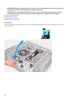
Replace the four screws #6-32 that secure the radiator and fan assembly to the chassis.
 |
View all Dell Alienware Aurora R12 manuals
Add to My Manuals
Save this manual to your list of manuals |
Page 69 highlights
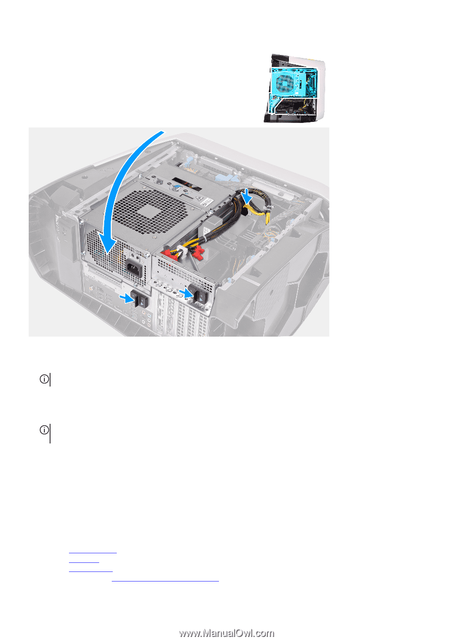
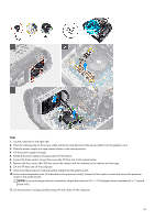
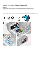
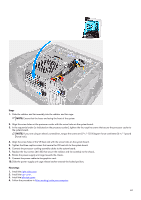
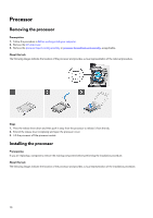
Steps 1. Slide the radiator and fan assembly into the radiator and fan cage. NOTE: Ensure that the hoses are facing the front of the system 2. Align the screw holes on the processor cooler with the screw holes on the system board. 3. In the sequential order (as indicated on the processor cooler), tighten the four captive screws that secure the processor cooler to the system board. NOTE: If your are using an electric screwdriver, torque the screws at 6.9 +/-1.15 kilogram-force centimeter (6 +/-1 pound force inch). 4. Align the screw holes of the VR heat sink with the screw holes on the system board. 5. Tighten the three captive screws that secure the VR heat sink to the system board. 6. Connect the processor-cooling assembly cables to the system board. 7. Replace the four screws (#6-32) that secure the radiator and fan assembly to the chassis. 8. Rotate the power-supply unit cage towards the chassis. 9. Connect the power cables to the graphics card. 10. Slide the power-supply unit cage release latches towards the locked position. Next steps 1. Install the right-side cover. 2. Install the top-cover. 3. Install the left-side cover. 4. Follow the procedure in After working inside your computer. 69
-
 1
1 -
2
-
3
-
4
-
5
-
6
-
7
-
8
-
9
-
10
-
11
-
12
-
13
-
14
-
15
-
16
-
17
-
18
-
19
-
20
-
21
-
22
-
23
-
24
-
25
-
26
-
27
-
28
-
29
-
30
-
31
-
32
-
33
-
34
-
35
-
36
-
37
-
38
-
39
-
40
-
41
-
42
-
43
-
44
-
45
-
46
-
47
-
48
-
49
-
50
-
51
-
52
-
53
-
54
-
55
-
56
-
57
-
58
-
59
-
60
-
61
-
62
-
63
-
 64
64 -
 65
65 -
 66
66 -
 67
67 -
 68
68 -
 69
69 -
 70
70 -
 71
71 -
 72
72 -
 73
73 -
 74
74 -
75
-
76
-
77
-
78
-
79
-
80
-
81
-
82
-
83
-
84
-
85
-
86
-
87
-
88
-
89
-
90
-
91
-
92
-
93
-
94
-
95
-
96
-
97
-
98
-
99
-
100
-
101
-
102
-
103
-
104
 |
 |