Dell Alienware Aurora R12 Service Manual - Page 86
System board, Removing the system board
 |
View all Dell Alienware Aurora R12 manuals
Add to My Manuals
Save this manual to your list of manuals |
Page 86 highlights
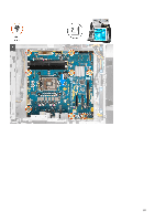
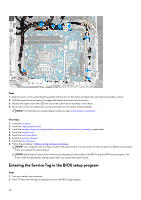
Steps 1. Align the screw holes on the power-button module with the screw holes on the front bezel. 2. Replace the two screws (M2x4) that secure the power-button module to the front bezel. 3. Connect the cables to the power-button module. Next steps 1. Install the front bezel. 2. Install the top-cover. 3. Install the right-side cover. 4. Install the left-side cover. 5. Follow the procedure in After working inside your computer. System board Removing the system board Prerequisites 1. Follow the procedure in Before working inside your computer. NOTE: Your computer's Service Tag is stored in the system board. You must enter the Service Tag in the BIOS setup program after you replace the system board. NOTE: Replacing the system board removes any changes you have made to the BIOS using the BIOS setup program. You must make the appropriate changes again after you replace the system board. NOTE: Before disconnecting the cables from the system board, note the location of the connectors so that you can reconnect the cables correctly after you replace the system board. 2. Remove the left-side cover. 3. Remove the memory modules. 4. Remove the solid-state drive. 5. Remove the wireless card. 6. Remove the processor liquid-cooling assembly or processor fan and heat-sink assembly, as applicable. 86
-
 1
1 -
2
-
3
-
4
-
5
-
6
-
7
-
8
-
9
-
10
-
11
-
12
-
13
-
14
-
15
-
16
-
17
-
18
-
19
-
20
-
21
-
22
-
23
-
24
-
25
-
26
-
27
-
28
-
29
-
30
-
31
-
32
-
33
-
34
-
35
-
36
-
37
-
38
-
39
-
40
-
41
-
42
-
43
-
44
-
45
-
46
-
47
-
48
-
49
-
50
-
51
-
52
-
53
-
54
-
55
-
56
-
57
-
58
-
59
-
60
-
61
-
62
-
63
-
64
-
65
-
66
-
67
-
68
-
69
-
70
-
71
-
72
-
73
-
74
-
75
-
76
-
77
-
78
-
79
-
80
-
 81
81 -
 82
82 -
 83
83 -
 84
84 -
 85
85 -
 86
86 -
 87
87 -
 88
88 -
 89
89 -
 90
90 -
 91
91 -
92
-
93
-
94
-
95
-
96
-
97
-
98
-
99
-
100
-
101
-
102
-
103
-
104
 |
 |
