Dell Alienware m15 R2 Service Manual - Page 21
display assembly need to be replaced, the entire display assembly is to be replaced.
 |
View all Dell Alienware m15 R2 manuals
Add to My Manuals
Save this manual to your list of manuals |
Page 21 highlights
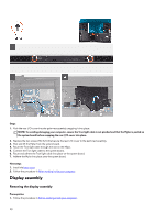
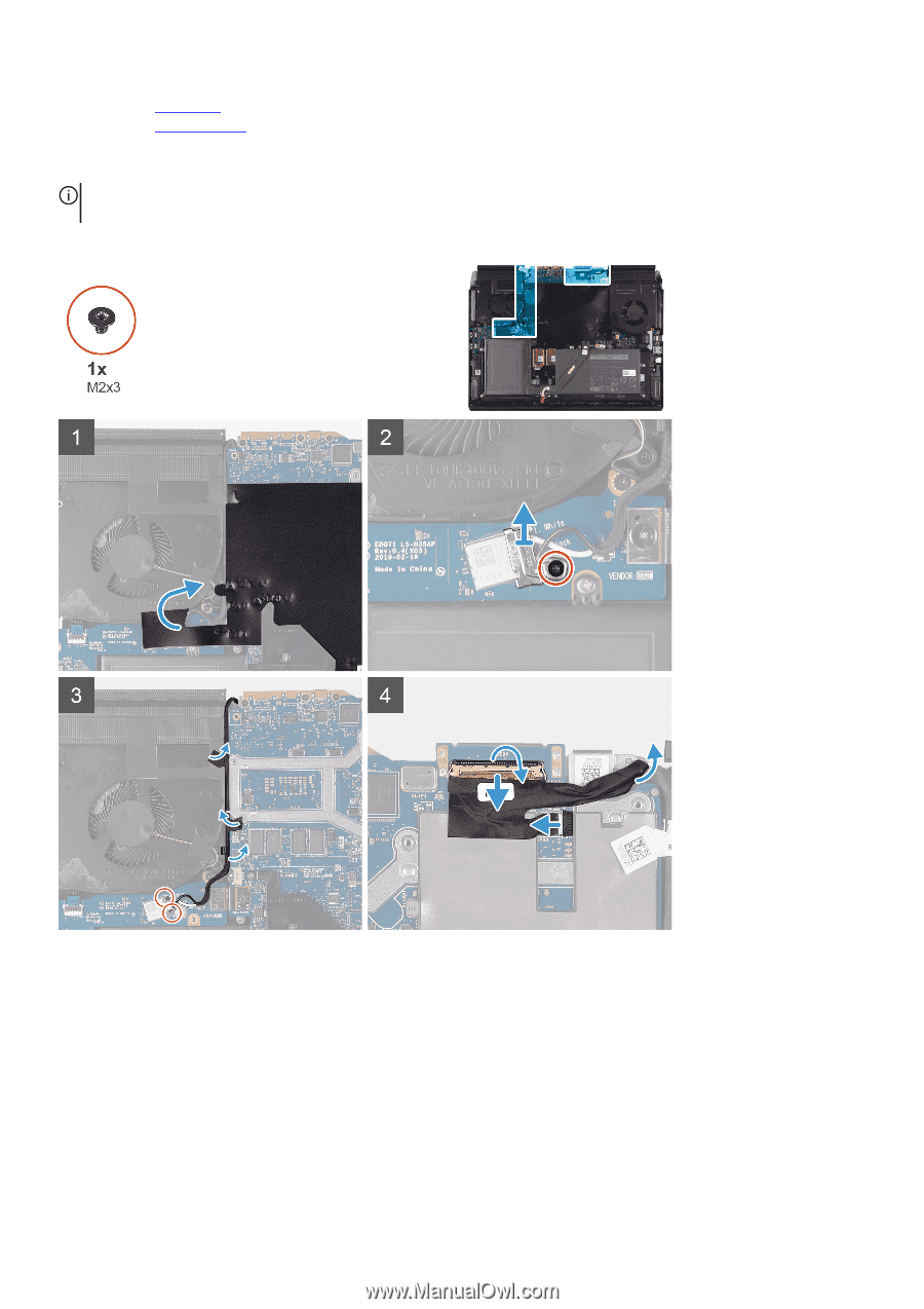
2. Remove the base cover. 3. Remove the rear I/O-cover. About this task NOTE: The display assembly is a Hinge-up Display (HUD) and cannot be further disassembled. If components within the display assembly need to be replaced, the entire display assembly is to be replaced. The following image indicates the location of the display assembly and provides a visual representation of the removal procedure. 21
-
 1
1 -
2
-
3
-
4
-
5
-
6
-
7
-
8
-
9
-
10
-
11
-
12
-
13
-
14
-
15
-
 16
16 -
 17
17 -
 18
18 -
 19
19 -
 20
20 -
 21
21 -
 22
22 -
 23
23 -
 24
24 -
 25
25 -
 26
26 -
27
-
28
-
29
-
30
-
31
-
32
-
33
-
34
-
35
-
36
-
37
-
38
-
39
-
40
-
41
-
42
-
43
-
44
-
45
-
46
-
47
-
48
-
49
-
50
-
51
-
52
-
53
-
54
-
55
-
56
-
57
-
58
-
59
-
60
-
61
-
62
-
63
-
64
-
65
-
66
-
67
-
68
-
69
-
70
 |
 |
2.
Remove the
base cover
.
3.
Remove the
rear I/O-cover
.
About this task
NOTE: The display assembly is a Hinge-up Display (HUD) and cannot be further disassembled. If components within the
display assembly need to be replaced, the entire display assembly is to be replaced.
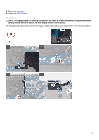
The following image indicates the location of the display assembly and provides a visual representation of the removal procedure.
21