Dell Alienware m15 R2 Service Manual - Page 8
Removing and installing components, Recommended tools, Screw list
 |
View all Dell Alienware m15 R2 manuals
Add to My Manuals
Save this manual to your list of manuals |
Page 8 highlights
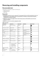
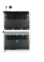
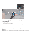
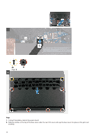
Removing and installing components Recommended tools The procedures in this document may require the following tools: • Philips screwdriver #1 • Flat-head screwdriver • Plastic scribe Screw list NOTE: When removing screws from a component, it is recommended to note the screw type, the quantity of screws, and then place them in a screw storage box. This is to ensure that the correct number of screws and correct screw type is restored when the component is replaced. NOTE: Some computers have magnetic surfaces. Ensure that the screws are not left attached to such surface when replacing a component. NOTE: Screw color may vary with the configuration ordered. Table 1. Screw list Component Base cover Secured to Palm-rest assembly Screw type M2.5x5 Quantity 2 Screw image M.2 connector shield M.2 2230 solid-state drive M.2 2230 mounting bracket M.2 2280 solid-state drive Back cover System board M.2 2230 mounting bracket Palm-rest assembly Palm-rest assembly Palm-rest assembly M2x4.5 M2x3 M2x3 M2x3 M2.5x5 1 1 per M.2 2230 solidstate drive 1 per M.2 2230 solidstate drive 1 per M.2 2280 solidstate drive 2 Wireless-card bracket Left I/O-board M2x3 1 Display assembly Palm-rest assembly M2.5x5 6 Battery • Palm-rest assembly M2x4.5 6 • System board • Left I/O-board • Right I/O-board Keyboard-backlight Keyboard-controller M2x1.9 2 cable board Left I/O-board • System board M2x3 2 connector • Left I/O-board 8
-
 1
1 -
2
-
 3
3 -
 4
4 -
 5
5 -
 6
6 -
 7
7 -
 8
8 -
 9
9 -
 10
10 -
 11
11 -
 12
12 -
 13
13 -
14
-
15
-
16
-
17
-
18
-
19
-
20
-
21
-
22
-
23
-
24
-
25
-
26
-
27
-
28
-
29
-
30
-
31
-
32
-
33
-
34
-
35
-
36
-
37
-
38
-
39
-
40
-
41
-
42
-
43
-
44
-
45
-
46
-
47
-
48
-
49
-
50
-
51
-
52
-
53
-
54
-
55
-
56
-
57
-
58
-
59
-
60
-
61
-
62
-
63
-
64
-
65
-
66
-
67
-
68
-
69
-
70
 |
 |
