Dell Alienware m15 R2 Service Manual - Page 43
Connect the coin-cell battery cable to the system board.
 |
View all Dell Alienware m15 R2 manuals
Add to My Manuals
Save this manual to your list of manuals |
Page 43 highlights
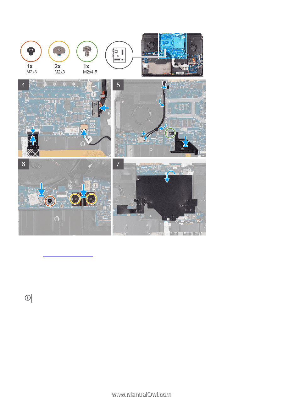
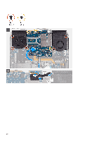
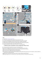
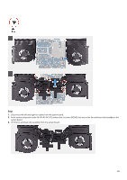
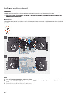
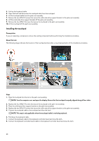
Steps 1. Install the fan and heat-sink assembly. 2. Connect the touchpad cable to the system board and close the latch. 3. Turn the system board over and place the system board on the palm-rest assembly. 4. Replace the five (M2.5x5) screws that secure the fans to the palm-rest assembly. 5. Replace the four (M2x3) screws that secure the system board to the palm-rest assembly. 6. Connect the touchpad cable to the touchpad and close the latch. 7. Connect the Tobii eye tracker cable to the connector on the system board. NOTE: This step is only applicable to computers shipped with a Tobii eye tracker. 8. Connect the G-sensor cable to the connector on the system board. 9. Connect the display cable to the connector on the system board and close the latch. 10. Connect the keyboard-controller board-cable to the system board and close the latch. 11. Connect the coin-cell battery cable to the system board. 12. Connect the power-adapter port cable to the system board. 13. Using the tab on the M.2 connector shield and the slot on the system board, align the screw hole of the M.2 connector shield with the screw hole on the system board. 14. Replace the screw (M2x4.5) that secures the M.2 connector shield to the system board. 15. Using the alignment pins, connect the left I/O-board cable to the left I/O-board and the system board. 43
-
 1
1 -
2
-
3
-
4
-
5
-
6
-
7
-
8
-
9
-
10
-
11
-
12
-
13
-
14
-
15
-
16
-
17
-
18
-
19
-
20
-
21
-
22
-
23
-
24
-
25
-
26
-
27
-
28
-
29
-
30
-
31
-
32
-
33
-
34
-
35
-
36
-
37
-
 38
38 -
 39
39 -
 40
40 -
 41
41 -
 42
42 -
 43
43 -
 44
44 -
 45
45 -
 46
46 -
 47
47 -
 48
48 -
49
-
50
-
51
-
52
-
53
-
54
-
55
-
56
-
57
-
58
-
59
-
60
-
61
-
62
-
63
-
64
-
65
-
66
-
67
-
68
-
69
-
70
 |
 |