Dell EqualLogic PS6210S PS6210 Hardware Owners Manual - Page 37
Maintaining Power Supply and Cooling Modules, About Power Supplies
 |
View all Dell EqualLogic PS6210S manuals
Add to My Manuals
Save this manual to your list of manuals |
Page 37 highlights
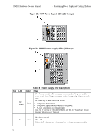
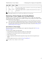
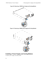
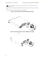
4 Maintaining Power Supply and Cooling Modules The array can support two hot-swappable power supply and cooling modules. The array is capable of operating with one power supply cooling module temporarily, but both power supply cooling modules are required to maintain long-term cooling and reliability of the array. About Power Supplies The PS Series array receives power from two power supplies (PSUs). Depending on the chassis size, your array contains either: • Two 700-watt PSUs, used in the 2U array. Each 700W power supply contains two cooling fans. • Two 1080-watt PSUs, used in the 4U array. Each 1080W power supply contains four cooling fans. The cooling fans contained in the power supply unit are not serviceable. If fan failures occur, the entire power supply unit must be replaced. Identifying Power Supply Failures You can identify a power supply and cooling module failure by any or all of the following methods: • LEDs on the power supply and cooling modules. See Power Supply LEDs on page 31 for details. • Messages on the console, in the event log, or in the Group Manager GUI Alarms panel. • Group Manager GUI and CLI output. The GUI Member Enclosure window or the CLI member select member name show enclosure command shows a power supply and cooling module failure. When viewing the rear of the array, power supply 0 is on the left and power supply 1 is on the right. Power Supply LEDs The power supplies and cooling modules have LEDs that indicate their status. Figure 28 and Figure 29 illustrate the power supply LEDs. Table 8 describes these LEDs. 31
-
 1
1 -
2
-
3
-
4
-
5
-
6
-
7
-
8
-
9
-
10
-
11
-
12
-
13
-
14
-
15
-
16
-
17
-
18
-
19
-
20
-
21
-
22
-
23
-
24
-
25
-
26
-
27
-
28
-
29
-
30
-
31
-
 32
32 -
 33
33 -
 34
34 -
 35
35 -
 36
36 -
 37
37 -
 38
38 -
 39
39 -
 40
40 -
 41
41 -
 42
42 -
43
-
44
-
45
-
46
-
47
-
48
 |
 |
