Dell EqualLogic PS6210S PS6210 Hardware Owners Manual - Page 38
W Power Supply LEDs 2U Arrays, Table 8: Power Supply LED Descriptions
 |
View all Dell EqualLogic PS6210S manuals
Add to My Manuals
Save this manual to your list of manuals |
Page 38 highlights
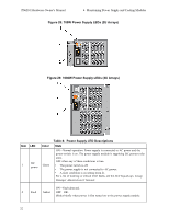
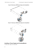
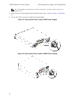
PS6210 Hardware Owner's Manual 4 Maintaining Power Supply and Cooling Modules Figure 28: 700W Power Supply LEDs (2U Arrays) Figure 29: 1080W Power Supply LEDs (4U Arrays) Item 1 LED DC power Color Green Table 8: Power Supply LED Descriptions State ON-Normal operation. Power supply is connected to AC power and the power switch is on. The power supply module is supplying DC power to the array. OFF when any of these conditions is true: • The power switch is off. • The power supply is not connected to AC power. • A fault condition is occurring (item 2). For a list of warning or critical level faults, see the Dell EqualLogic Group Manager Administrator's Manual. ON-Fault detected. 2 Fault Amber OFF-OK. Blinks briefly when power is first turned on to the power supply module. 32
-
 1
1 -
2
-
3
-
4
-
5
-
6
-
7
-
8
-
9
-
10
-
11
-
12
-
13
-
14
-
15
-
16
-
17
-
18
-
19
-
20
-
21
-
22
-
23
-
24
-
25
-
26
-
27
-
28
-
29
-
30
-
31
-
32
-
 33
33 -
 34
34 -
 35
35 -
 36
36 -
 37
37 -
 38
38 -
 39
39 -
 40
40 -
 41
41 -
 42
42 -
 43
43 -
44
-
45
-
46
-
47
-
48
 |
 |
