Dell EqualLogic PS6210XV PS6210 Installation and Setup Guide - Page 13
Steps for Mounting an Array in a Rack, Optional Hardware
 |
View all Dell EqualLogic PS6210XV manuals
Add to My Manuals
Save this manual to your list of manuals |
Page 13 highlights
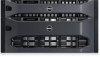
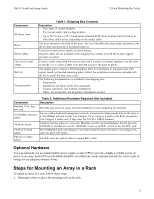
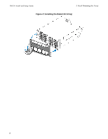
PS6210 Install and Setup Guide 2 Rack Mounting the Array Component PS Series Array Bezel Power cables One or two serial cables Rail kit Documentation Table 1: Shipping Box Contents Description • Two Type 15 control modules • Two power supply and cooling modules • Up to 24 2.5-inch or 24 3.5-inch Serial Attached SCSI (SAS, Nearline SAS [NL-SAS], or Solid State (SSD) drives, depending on the model suffix The bezel mounts to the front of the array. The bezel identifies the array model and protects the drives from unauthorized or accidental removal. Connects an array power supply to power sources. If power cables are not included in the shipping box, contact your PS Series array support provider or reseller. Creates a serial connection between an array and a console or terminal emulator. Use the cable to run the setup utility if there is no network access to the array or group. The shipping box contains a Dell ReadyRails II kit for installation in four-post racks with square, round, or threaded mounting holes. Follow the installation instructions included with the kit to install the array into a rack. The following documentation is included in the shipping box: • Setup poster • Installation and Setup Guide (this document) • License, regulatory, and warranty information • Safety, Environmental, and Regulatory Information booklet Component Standard 19-in. fourpost rack 10/100Mbps Ethernet cables Network switch CAT6 or CAT6A cables Optical or copper cables Table 2: Additional Hardware Required (Not Included) Description Provides easy access to arrays and other hardware in your computing environment. For use with a dedicated management network. Connects the Management port on the array to a 10/100Mbps network switch. Use Category 5E or Category 6 cables with RJ45 connectors. Use Category 5 cables only if they meet the TIA/EIA TSB95 standard. Connects devices (array) to a network. Multiple switches are recommended. Switch provides 10GBASE-T interfaces to use the 10GBASE-T port, or an SFP+ switch to use the SFP+ port. For 10GBASE-T port, use Category 6 (or better) cable for up to 55 meters. Use Category 6A cable for up to 100 meters. For SFP+ port, use optical cable or copper SFP+ cable. Optional Hardware You can optionally use an uninterruptible power supply system (UPS) to provide a highly available source of power to an array. Each UPS (not included) should be on a different circuit and must provide the correct type of voltage for an adequate amount of time. Steps for Mounting an Array in a Rack To mount an array in a rack, follow these steps: 1. Determine where to place the mounting rails in the rack. 5
-
 1
1 -
2
-
3
-
4
-
5
-
6
-
7
-
 8
8 -
 9
9 -
 10
10 -
 11
11 -
 12
12 -
 13
13 -
 14
14 -
 15
15 -
 16
16 -
 17
17 -
 18
18 -
19
-
20
-
21
-
22
-
23
-
24
-
25
-
26
-
27
-
28
-
29
-
30
-
31
-
32
-
33
-
34
-
35
-
36
-
37
-
38
-
39
-
40
-
41
-
42
-
43
-
44
-
45
-
46
 |
 |
