Dell EqualLogic PS6210XV PS6210 Installation and Setup Guide - Page 17
Connecting the Array Cables, Network Requirements and Recommendations
 |
View all Dell EqualLogic PS6210XV manuals
Add to My Manuals
Save this manual to your list of manuals |
Page 17 highlights
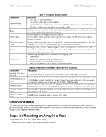
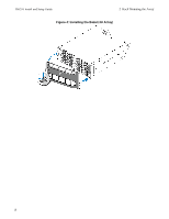
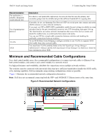
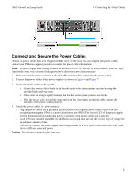
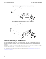
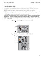
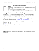
3 Connecting the Array Cables After you install the array in a rack, you must connect the network and power cables and, optionally, the serial cables. First, review the network recommendations in Minimum and Recommended Cable Configurations on page 10. The following list describes the general steps for connecting the array to power and the network: 1. Connect the power cables. Do not turn on power to the array at this time. See Connect and Secure the Power Cables on page 11. 2. Connect the array to the network. See Connect the Array to the Network on page 12. 3. Turn on power to the array. See Turning On the Array on page 13. The following sections describe these steps in detail. After completing the steps, see Software Configuration on page 17. Network Requirements and Recommendations The minimum network configuration for a PS Series array consists of a connection between Ethernet 0 on each control module and a computer connected to a network switch. To increase performance and availability, configure multiple network interfaces on an array and connect them to multiple switches. Network recommendations are described in Table 3. In addition, all the usual rules for proper network configuration apply to PS Series arrays. For more information about network requirements, see the Dell EqualLogic Configuration Guide on the Dell TechCenter website at en.community.dell.com/techcenter/storage/w/wiki/2639.equallogic-configuration-guide.aspx. General network configuration is beyond the scope of this manual. Table 3: Network Recommendations Recommendation Description Connect arrays and computers to a switched network and ensure that all network connections between computers and arrays are 10GbE. Switched 10GbE network Use optical cables with optical SFP+ plug-in modules, or copper cables with integrated SFP+ modules. 10GBASE-T requires Cat 6 minimally, but Cat 6A is recommended. Requires a switch with 10GBASE-T interfaces to use the 10GBASE-T port, or an SFP+ switch to use the SFP+ port. For increased bandwidth and availability, connect each control module to two different switches. Multiple network The switches must be connected using interswitch links or by stacking capability. The links connections to different must have sufficient bandwidth to handle the iSCSI traffic. Review the EqualLogic network switches Configuration Guide for interswitch link sizing recommendations. After connecting the network interfaces, use the Group Manager GUI or CLI to assign an IP address, netmask, and gateway address to each interface. Management network (optional) Connect the management ports on both control modules to a 10/100Mbps network switch to keep management traffic separate from iSCSI traffic. Access to the group IP In a multi-subnet group, each configured network interface should have access to the subnet address (Hosts) on which the group IP address resides. 9
-
 1
1 -
2
-
3
-
4
-
5
-
6
-
7
-
8
-
9
-
10
-
11
-
 12
12 -
 13
13 -
 14
14 -
 15
15 -
 16
16 -
 17
17 -
 18
18 -
 19
19 -
 20
20 -
 21
21 -
 22
22 -
23
-
24
-
25
-
26
-
27
-
28
-
29
-
30
-
31
-
32
-
33
-
34
-
35
-
36
-
37
-
38
-
39
-
40
-
41
-
42
-
43
-
44
-
45
-
46
 |
 |
