Dell EqualLogic PS6210XV PS6210 Installation and Setup Guide - Page 21
Turning On the Array, AC Power Supply Switch and LEDs 2U Array
 |
View all Dell EqualLogic PS6210XV manuals
Add to My Manuals
Save this manual to your list of manuals |
Page 21 highlights
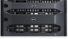
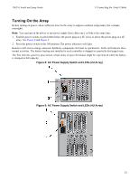
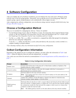
PS6210 Install and Setup Guide 3 Connecting the Array Cables Turning On the Array Before turning on power, allow sufficient time for the array to adjust to ambient temperature (for example, overnight). Note: You can turn on the power to one power supply first (either one), or both at the same time. 1. Find the power switch, located either below the power plug on a 2U array or above the power plug on a 4U array. See Figure 8 and Figure 9. 2. Press the power switch to the ON position. The power indicators will light. Batteries will start to charge and some hardware components will start to synchronize. LEDs will indicate these normal activities. The battery backup unit installed in each controller is shipped in a partially discharged state. The first time the system is powered on, a boot delay of up to 30 minutes might be experienced while the battery is charged to full capacity. Figure 8: AC Power Supply Switch and LEDs (2U Array) Figure 9: AC Power Supply Switch and LEDs (4U Array) 13
-
 1
1 -
2
-
3
-
4
-
5
-
6
-
7
-
8
-
9
-
10
-
11
-
12
-
13
-
14
-
15
-
 16
16 -
 17
17 -
 18
18 -
 19
19 -
 20
20 -
 21
21 -
 22
22 -
 23
23 -
 24
24 -
 25
25 -
 26
26 -
27
-
28
-
29
-
30
-
31
-
32
-
33
-
34
-
35
-
36
-
37
-
38
-
39
-
40
-
41
-
42
-
43
-
44
-
45
-
46
 |
 |
