Dell EqualLogic PS6210XV PS6210 Installation and Setup Guide - Page 22
Set Up a Serial Connection to the Array, Table 4: Power Supply LED Descriptions
 |
View all Dell EqualLogic PS6210XV manuals
Add to My Manuals
Save this manual to your list of manuals |
Page 22 highlights
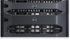
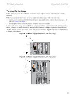
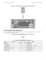
PS6210 Install and Setup Guide 3 Connecting the Array Cables Callout 1 2 3 Table 4: Power Supply LED Descriptions Description Power Supply status. This LED is lit (green) when the switch is on and the power supply is providing power to the array. Error. This LED is lit (amber) if the power supply has a problem. Input Power. This LED is lit (green) as long as main power is connected to the power supply. Set Up a Serial Connection to the Array If you plan to use the setup utility to configure the software, you must set up a serial connection between the array and a computer. If you plan to use the Remote Setup wizard, you do not need a serial connection. For information about Remote Setup wizard requirements, see the Host Integration Tool for Microsoft® Installation and User's Guide or the Host Integration Tool for Linux® Installation and User's Guide. The serial cable shipped with the array is a standard null-modem cable with a female DB9 connector on each end. You might have to make or buy an adapter cable (one DB9 connector and one RJ45 connector) to connect the array to some terminal server models. See Serial Cable Pinout Information on page 15. Attach the cable to the serial port on the active control module and to a console terminal or a computer running a terminal emulator. The active control module has two green LEDS and the secondary control module has one green and one amber LED. See Figure 10 (not to scale). The serial connection must have the following characteristics: • 9600 baud • One STOP bit • No parity • 8 data bits • No flow control Note: Keep the serial cable. You need the serial cable to manage the group, or a specific array, if there is no network access. 14
-
 1
1 -
2
-
3
-
4
-
5
-
6
-
7
-
8
-
9
-
10
-
11
-
12
-
13
-
14
-
15
-
16
-
 17
17 -
 18
18 -
 19
19 -
 20
20 -
 21
21 -
 22
22 -
 23
23 -
 24
24 -
 25
25 -
 26
26 -
 27
27 -
28
-
29
-
30
-
31
-
32
-
33
-
34
-
35
-
36
-
37
-
38
-
39
-
40
-
41
-
42
-
43
-
44
-
45
-
46
 |
 |
