Dell Force10 S25-01-GE-24P Installing the S25P System - Page 11
System Status, LED Displays
 |
View all Dell Force10 S25-01-GE-24P manuals
Add to My Manuals
Save this manual to your list of manuals |
Page 11 highlights
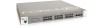
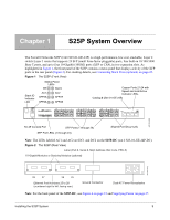
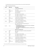
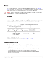
System Status S25P status can be derived in several ways, including physical LED displays and boot menu options, both discussed here, along with CLI show commands,and SNMP traps. For details on those options, see the Command Reference and Configuration Guide for your software (FTOS or SFTOS). LED Displays As shown in Figure 1, the S25P front panel contains several sets of LEDs: • Stack ID: This is the LED at the far left of the front panel labeled "STACK ID". See Stack ID in Table 3. For more on unit numbering, see Stacking on page 24. • Status indicator LEDs on the left side of the front panel, described in Table 4. • Each port has status indicator LEDs, described in Table 3. Table 3 Port LED Displays Feature Description 10/100/1000 Port LED* Speed LED (left side of each port) Green - A valid 1000Mbps link is established on this port. Amber - A valid 100Mbps link is established on this port. Off - No link or a valid 10Mbps link is established on this port. Link/Active LED (right side of each port) Green - Link up on this port Blinking Green - Activity, transmitting, or receiving packet at this port Off - No link detected at this port SFP Port LED* Link/Activity LED Green - A valid 1000Mbps link is established on this port. Blinking Green - Activity, transmitting or receiving packet in link up state Solid Amber- A valid 100Mbps link is established on this port. Blinking Amber - Activity, transmitting, or receiving packet in link up, 100Mbps state. Off - No link detected at this port XFP Port LED Link/Activity LED (Each XFP port has a status LED on the module and in the Status Display at the left front of the switch) Green - Link up on this port Blinking Green - Activity, transmitting or receiving packet in link up state Off - No Link detected at this port * The LEDs for a 10/100/1000 copper port (numbered 21 through 24) are inactive if the shared SFP port (also labeled 21 through 24) is enabled. Note: As suggested by the footnote above, the fiber SFP ports have priority over the four 10/100/1000 ports with the same number. Installing the S25P System 11
-
 1
1 -
2
-
3
-
4
-
5
-
 6
6 -
 7
7 -
 8
8 -
 9
9 -
 10
10 -
 11
11 -
 12
12 -
 13
13 -
 14
14 -
 15
15 -
 16
16 -
17
-
18
-
19
-
20
-
21
-
22
-
23
-
24
-
25
-
26
-
27
-
28
-
29
-
30
-
31
-
32
-
33
-
34
-
35
-
36
-
37
-
38
-
39
-
40
-
41
-
42
-
43
-
44
-
45
-
46
-
47
-
48
 |
 |