Dell Force10 S25-01-GE-24P Installing the S25P System - Page 37
Waste Electrical and Electronic Equipment WEEE Directive for Recovery
 |
View all Dell Force10 S25-01-GE-24P manuals
Add to My Manuals
Save this manual to your list of manuals |
Page 37 highlights
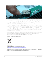
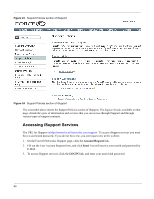
Waste Electrical and Electronic Equipment (WEEE) Directive for Recovery, Recycle and Reuse of IT and Telecommunications Products Force10 switches are labeled in accordance with European Directive 2002/96/EC concerning waste electrical and electronic equipment (WEEE). The Directive determines the framework for the return and recycling of used appliances as applicable throughout the European Union. This label, as shown in Figure 21 on page 37 is applied to various products to indicate that the product is not to be thrown away, but rather reclaimed upon end of life per this Directive. Figure 21 The European WEEE symbol In accordance with the European WEEE Directive, electrical and electronic equipment (EEE) is to be collected separately and to be reused, recycled, or recovered at end of life. Users of EEE with the WEEE marking per Annex IV of the WEEE Directive, as shown above, must not dispose of end of life EEE as unsorted municipal waste, but use the collection framework available to customers for the return, recycling and recovery of WEEE. Customer participation is important to minimize any potential effects of EEE on the environment and human health due to the potential presence of hazardous substances in EEE. Force10 Networks products, which fall within the scope of the WEEE, are labeled with the crossed-out wheelie-bin symbol, as shown above, as required by WEEE. For information on Force10 product recycling offerings, see the WEEE Recycling instructions on iSupport at: https://www.force10networks.com/CSPortal20/Support/WEEEandRecycling.pdf. For more information, contact the Force10 Technical Assistance Center (TAC) (see Contacting the Technical Assistance Center on page 41). Notice to Recyclers To open the case: 1 Remove the small phillips screws that connect the top to the body. There should be three evenly spaced across the rear and three evenly spaced along each side. 2 Slide the top backwards until its front flange slides free of the faceplate, then lift it off. To remove the lithium closed-cell clock battery (clearly visible towards the right rear of switch): 1 Insert a small, flat screw driver blade under the battery and in one of the slots of the plastic retainer underneath the battery. 2 Lever the battery up against the coin cell clip (the hold-down lead on top of the battery) far enough to provide room for the battery to be lifted above the edge of its retainer, as shown in the photograph, below. Installing the S25P System 37
-
 1
1 -
2
-
3
-
4
-
5
-
6
-
7
-
8
-
9
-
10
-
11
-
12
-
13
-
14
-
15
-
16
-
17
-
18
-
19
-
20
-
21
-
22
-
23
-
24
-
25
-
26
-
27
-
28
-
29
-
30
-
31
-
 32
32 -
 33
33 -
 34
34 -
 35
35 -
 36
36 -
 37
37 -
 38
38 -
 39
39 -
 40
40 -
 41
41 -
 42
42 -
43
-
44
-
45
-
46
-
47
-
48
 |
 |