Dell Force10 S25-01-GE-24P Installing the S25P System - Page 25
Using FTOS Stacking Commands, Connecting Stack Ports (optional), FTOS Command Reference
 |
View all Dell Force10 S25-01-GE-24P manuals
Add to My Manuals
Save this manual to your list of manuals |
Page 25 highlights
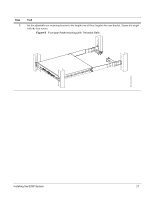
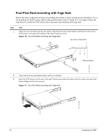
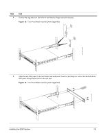
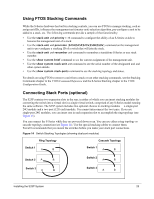
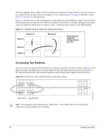
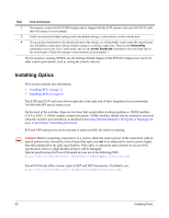
Using FTOS Stacking Commands While the S-Series hardware has built-in stacking controls, you can use FTOS to manage stacking, such as assign unit IDs, influence the management unit (master unit) selection algorithm, pre-configure a unit to be added to a stack, etc. The following commands provide a sample of that functionality: • Use the stack-unit unit priority 1-14 command to configure the ability of an S-Series switch to become the management unit of a stack. • Use the stack-unit unit provision {S25N|S25P|S25V|S50N|S50V} command on the management unit to pre-configure a stacking ID of a switch that will join the stack. • Use the stack-unit unit renumber unit command to renumber a standalone S-Series or any stack member. • Use the show system brief command to see the current assignment of the management unit. • Use the show system stack-unit unit command to see the serial number of the designated unit and other system details. • Use the show system stack-ports command to see the stacking topology and status. For details on using FTOS to remove a unit from a stack or use other stacking commands, see the Stacking Commands chapter in the FTOS Command Reference and the S-Series Stacking chapter in the FTOS Configuration Guide. Connecting Stack Ports (optional) The S25P contains two expansion slots in the rear, in either of which you can insert stacking modules for converting the switch into a virtual slot in a single virtual switch, comprised of any S-Series model running the same software. The S25P system includes two optional choices in stacking modules - a single-port 24G module and a two-port (12G each) module. You cannot interconnect the two types. If you use single-port 24G modules, you can insert one in each expansion slot to accomplish the ring topology (see Figure 15). You can connect the S-Series while they are powered down or up. You can use either a ring topology or cascade topology connection (see Figure 14). Use the special stacking cables to connect them. Force10 recommends that you mount the switches before you make your stack port connections. Figure 14 Switch Stacking Topologies (showing dual-port modules) Ring Topology Cascade Topology Switch 1 A B Switch 1 A B Switch 2 A B Switch 2 A B Switch 3 A B Switch 3 A B Installing the S25P System 25
-
 1
1 -
2
-
3
-
4
-
5
-
6
-
7
-
8
-
9
-
10
-
11
-
12
-
13
-
14
-
15
-
16
-
17
-
18
-
19
-
 20
20 -
 21
21 -
 22
22 -
 23
23 -
 24
24 -
 25
25 -
 26
26 -
 27
27 -
 28
28 -
 29
29 -
 30
30 -
31
-
32
-
33
-
34
-
35
-
36
-
37
-
38
-
39
-
40
-
41
-
42
-
43
-
44
-
45
-
46
-
47
-
48
 |
 |