Dell Force10 S25-01-GE-24P Installing the S25P System - Page 9
S25P System Overview - s25 dc
 |
View all Dell Force10 S25-01-GE-24P manuals
Add to My Manuals
Save this manual to your list of manuals |
Page 9 highlights
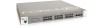
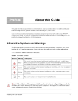
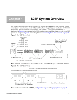
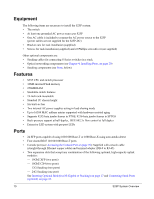
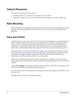
Chapter 1 S25P System Overview The Force10 Networks S25P (Cat# S25-01-GE-24P) is a high performance, low cost, stackable, Layer 2 switch/Layer 3 router that supports 24 SFP (small form-factor pluggable) ports, four built-in 10/100/1000 Base-T ports, and up to four 10-Gigabit (10GbE) ports (XFP or CX4), in two expansion slots. As highlighted in Figure 1, the front panel of the S25P contains a status panel that displays activity of the XFP ports in the rear panel (Figure 2). For stacking details, see Connecting Stack Ports (optional) on page 25. Figure 1 The S25P (Front View) Stack ID Indicator LED Status Panel LEDs OK Alarm AC1 AC2 XFP25 XFP27 XFP26 XFP28 Copper Ports 21-24 with Speed and Link/Active Indicator LEDs Catalog # (S25-01-GE-24P) Stack ID AC1 XFP25 XFP26 Alarm AC2 27 P28 S25-01-GE-24P fn00157s25P RJ-45 Console Port SFP Ports (1 through 24) SFP Port LEDs (1 through 24) Shared Port IDs (21-24) Note: The LEDs labeled AC1 and AC2 are DC1 and DC2 on the S25P-DC (cat.# S25-01-GE-24P-DC). Figure 2 The S25P (Rear View) Label (Part #, Serial #, MAC Address, Bar Code, FRU #) 10-Gigabit Modules or Stacking Modules (optional) fn00158s25P 28 27 26 25 Ethernet Port Numbers 25 to 28 (numbered right to left, facing rear) Ground Connector Dual AC Power Receptacles Note: For the back panel of the S25P-DC, see Figure 4 on page 15 and Supplying Power on page 27. Installing the S25P System 9
-
 1
1 -
2
-
3
-
 4
4 -
 5
5 -
 6
6 -
 7
7 -
 8
8 -
 9
9 -
 10
10 -
 11
11 -
 12
12 -
 13
13 -
 14
14 -
15
-
16
-
17
-
18
-
19
-
20
-
21
-
22
-
23
-
24
-
25
-
26
-
27
-
28
-
29
-
30
-
31
-
32
-
33
-
34
-
35
-
36
-
37
-
38
-
39
-
40
-
41
-
42
-
43
-
44
-
45
-
46
-
47
-
48
 |
 |