Dell Force10 Z9000 Dell Force10 Z9000 System Quick Start Guide - Page 12
Fans, Z9000 Specifications, Chassis Physical Design - dc
 |
View all Dell Force10 Z9000 manuals
Add to My Manuals
Save this manual to your list of manuals |
Page 12 highlights
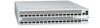
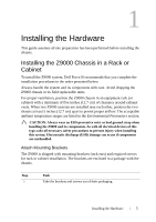
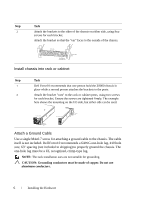
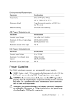
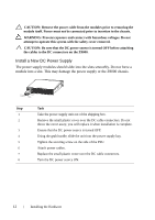
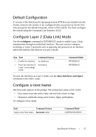
Step Task 1 Remove the small plastic cover from the DC connectors. 2 Ensure that the power source is turned off. Do not attach the DC cable to the DC connectors while the power source is on. 3 Attach the connectors to the PSUs, making sure that the connections are secure. 4 Replace the plastic cover over the DC connectors. As soon as the cable is connected between the Z9000 and the power source, the chassis is powered-up; there is no on/off switch. Fans The Z9000 comes from the factory with 1 power supply and 4 fan modules installed in the chassis. The fan modules are hot-swappable, if 2 or more fans are installed and running. The fan speed increases and decreases automatically based upon the system's state and temperature. The switch never intentionally turns off the fans. Use the show logging command to see the log messages. Z9000 Specifications Chassis Physical Design Parameter Height Width Depth Rack clearance required Thermal dissipation Specifications 3.48 inches (8.8 cm) 17.32 inches (44.0 cm) 24.00 inches (61.00 cm) Front: 5-inches (12.7 cm) Rear: 5-inches (12.7 cm) 2654 BTH/h (270W) 10 Installing the Hardware
-
 1
1 -
2
-
3
-
4
-
5
-
6
-
 7
7 -
 8
8 -
 9
9 -
 10
10 -
 11
11 -
 12
12 -
 13
13 -
 14
14 -
 15
15 -
 16
16 -
 17
17 -
18
-
19
-
20
-
21
-
22
-
23
-
24
 |
 |