Dell Force10 Z9000 Dell Force10 Z9000 System Quick Start Guide - Page 8
Install chassis into rack or cabinet, Attach a Ground Cable
 |
View all Dell Force10 Z9000 manuals
Add to My Manuals
Save this manual to your list of manuals |
Page 8 highlights
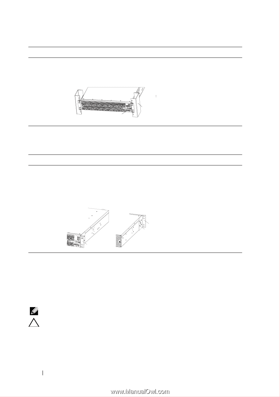
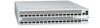
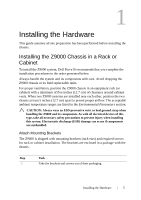
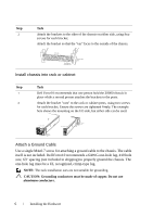
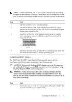
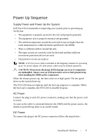
Step Task 2 Attach the brackets to the sides of the chassis on either side, using four screws for each bracket. Attach the bracket so that the "ear" faces to the outside of the chassis. I/O side Rack/Cabinet Mounting Ears Rack/Cabinet Post Install chassis into rack or cabinet Step Task 1 Dell Force10 recommends that one person hold the Z9000 chassis in place while a second person attaches the brackets to the posts. 2 Attach the bracket "ears" to the rack or cabinet posts, using two screws for each bracket. Ensure the screws are tightened firmly. The example here shows the mounting on the I/O side, but either side can be used. View from I/O side View from PSU side Connect to rack/cabinet (ears) Screws Connect to rack/cabinet (ears) Attach a Ground Cable Use a single M4x0.7 screw for attaching a ground cable to the chassis. The cable itself is not included. Dell Force10 recommends a 6AWG one-hole lug, #10 hole size, 63" spacing (not included in shipping) to properly ground the chassis. The one-hole lug must be a UL recognized, crimp-type lug. NOTE: The rack installation ears are not suitable for grounding. CAUTION: Grounding conductors must be made of copper. Do not use aluminum conductors. 6 Installing the Hardware
-
 1
1 -
2
-
 3
3 -
 4
4 -
 5
5 -
 6
6 -
 7
7 -
 8
8 -
 9
9 -
 10
10 -
 11
11 -
 12
12 -
 13
13 -
14
-
15
-
16
-
17
-
18
-
19
-
20
-
21
-
22
-
23
-
24
 |
 |