Dell I15RN-3647BK Service Manual - Page 30
System Board
 |
View all Dell I15RN-3647BK manuals
Add to My Manuals
Save this manual to your list of manuals |
Page 30 highlights
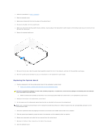
NOTICE: Socket pins are delicate. To avoid damage, ensure that the processor is aligned properly with the socket, and do not use excessive force when you install the process. Be careful not to touch or bend the pins on the system board. 4. Set the processor lightly in the socket and ensure that the processor is level in the socket. When the processor is positioned correctly, press it with minimal pressure to seat it. 5. When the processor is fully seated in the socket, close the processor cover. 6. Pivot the socket release lever back toward the socket and snap it into place to secure the processor. NOTICE: If you are not installing a processor upgrade kit from Dell, reuse the original heat sink assembly when you replace the processor. If you installed a processor replacement kit from Dell, return the original heat sink assembly and processor to Dell in the same package in which your replacement kit was sent. 7. Install the heat sink: a. Slide one end of the heat sink under the retention tab. b. Pull out the other retention tab and lower the heat sink until it fits securely in the base. NOTICE: Ensure the heat sink is correctly seated and secure. 8. Reinstall the retention module clips. 9. Lower the airflow shroud over the heat sink. 10. Reconnect the cooling fan power cable to the REAR FAN1 connector (see "System Board Components") on the system board. 11. Reconnect the power cable to the 12V PWR connector (see "System Board Components") on the system board. 12. Close the computer cover. NOTICE: To connect a network cable, first plug the cable into the network wall jack and then plug it into the computer. System Board CAUTION: Before you begin any of the procedures in this section, follow the safety instructions in the System Information Guide. NOTICE: The system board and metal tray are connected and are removed as one piece. Removing the System Board
-
 1
1 -
2
-
3
-
4
-
5
-
6
-
7
-
8
-
9
-
10
-
11
-
12
-
13
-
14
-
15
-
16
-
17
-
18
-
19
-
20
-
21
-
22
-
23
-
24
-
 25
25 -
 26
26 -
 27
27 -
 28
28 -
 29
29 -
 30
30 -
 31
31 -
 32
32 -
 33
33 -
 34
34 -
 35
35 -
36
-
37
-
38
-
39
-
40
-
41
-
42
-
43
-
44
-
45
-
46
-
47
-
48
-
49
-
50
 |
 |
