Dell Inspiron 1210 Service Manual - Page 29
Optical Drive
 |
View all Dell Inspiron 1210 manuals
Add to My Manuals
Save this manual to your list of manuals |
Page 29 highlights
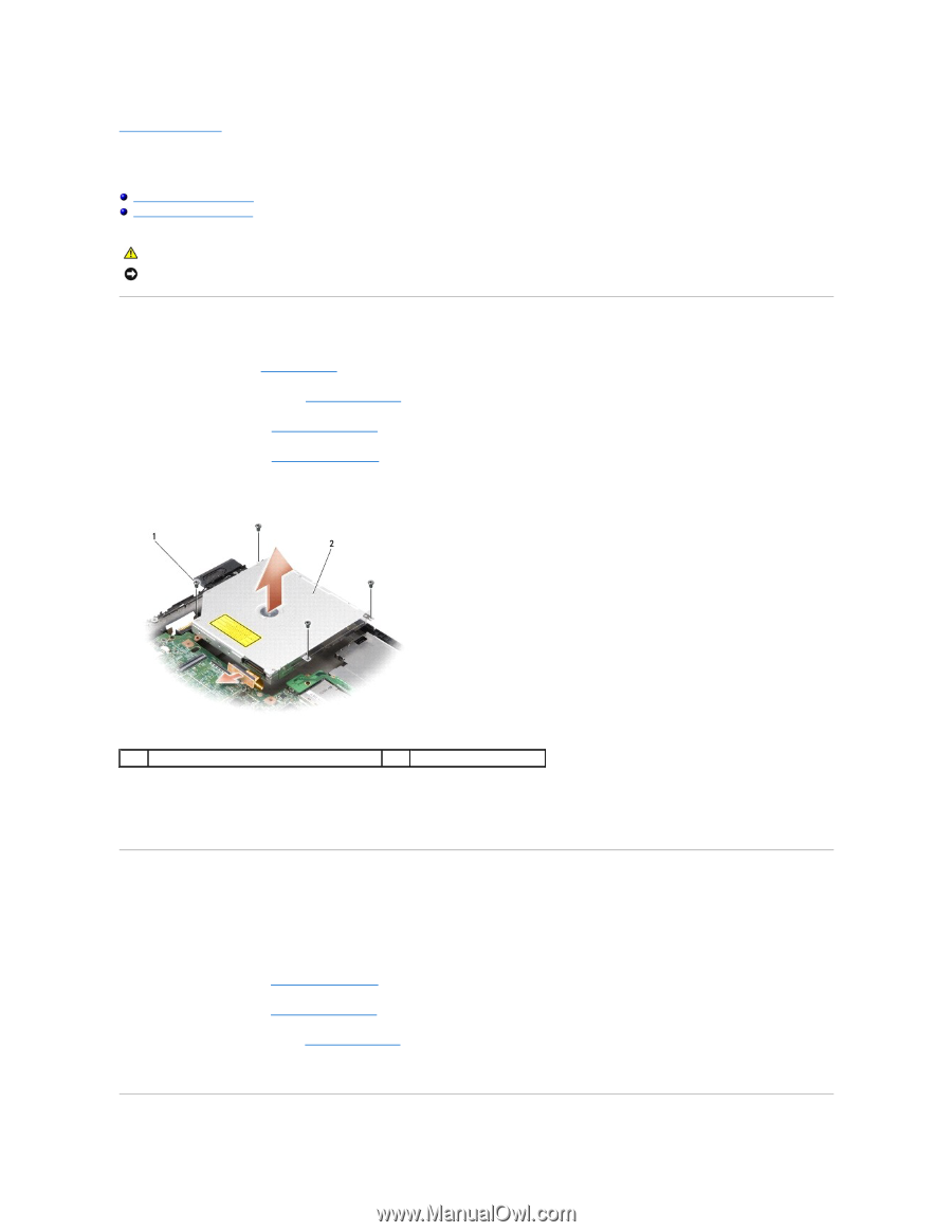
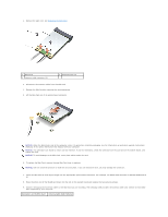
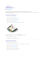
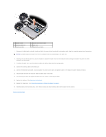
Back to Contents Page Optical Drive Dell™ Inspiron™ 1210 Service Manual Removing the Optical Drive Replacing the Optical Drive CAUTION: Before performing the following procedures, follow the safety instructions shipped with your computer. NOTICE: To avoid electrostatic discharge, ground yourself by using a wrist grounding strap or by periodically touching an unpainted metal surface (such as the back panel) on the computer. Removing the Optical Drive 1. Follow the procedures in Before You Begin. 2. Remove the display assembly (see Replacing the Display). 3. Remove the keyboard (see Replacing the Keyboard). 4. Remove the palm rest (see Replacing the Palm Rest). 5. Remove the four M2 x 3-mm screws that secure the optical drive to the computer base. 1 M2 x 3-mm screws (4) 2 optical drive 6. Lift the optical drive out of the computer base. 7. Pull the connector away from the back of the optical drive. Replacing the Optical Drive 1. Attach the connector to the back of the optical drive. 2. Replace the optical drive and the four M2 x 3-mm screws that secure the optical drive to the computer base. 3. Replace the palm rest (see Replacing the Palm Rest). 4. Replace the keyboard (see Replacing the Keyboard). 5. Replace the display assembly (see Replacing the Display). 6. Slide the battery into the battery bay, until it clicks into place.
-
 1
1 -
2
-
3
-
4
-
5
-
6
-
7
-
8
-
9
-
10
-
11
-
12
-
13
-
14
-
15
-
16
-
17
-
18
-
19
-
20
-
21
-
22
-
23
-
 24
24 -
 25
25 -
 26
26 -
 27
27 -
 28
28 -
 29
29 -
 30
30 -
 31
31 -
 32
32 -
 33
33 -
 34
34 -
35
-
36
-
37
-
38
 |
 |