Dell Inspiron 1210 Service Manual - Page 7
Replacing the Camera
 |
View all Dell Inspiron 1210 manuals
Add to My Manuals
Save this manual to your list of manuals |
Page 7 highlights
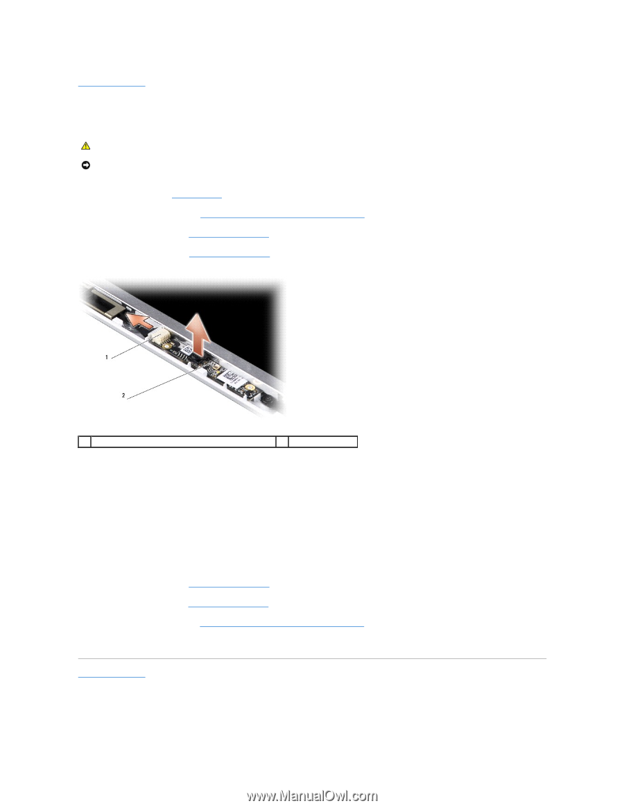
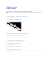
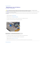
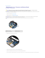
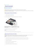
Back to Contents Page Replacing the Camera Dell™ Inspiron™ 1210 Service Manual CAUTION: Before working inside your computer, read the safety information that shipped with your computer. For additional safety best practices information, see the Regulatory Compliance Homepage at www.dell.com/regulatory_compliance. NOTICE: To avoid electrostatic discharge, ground yourself by using a wrist grounding strap or by periodically touching an unpainted metal surface (such as a connector on the back of the computer). 1. Follow the instructions in Before You Begin. 2. Remove the display assembly. See Follow the instructions in "Before You Begin" on page 9.. 3. Remove the display bezel. See Replacing the Display Bezel. 4. Remove the display panel. See Replacing the Display Panel. 1 2-in1 camera and LVDS cable connector 2 camera board 5. Remove the camera board out of the protrusions that secure it firmly to the display frame. 6. Disconnect the 2-in-1 camera and LVDS cable from its connector on the display frame. 7. Remove the camera board. 8. To replace the camera, connect 2-in-1 camera and LVDS cable to its connector. 9. Align the camera board with the protrusions on the display frame. 10. Press the board gently until it sits firmly in the display frame. 11. Replace the display panel. See Replacing the Display Panel. 12. Replace the display bezel. See Replacing the Display Bezel. 13. Replace the display assembly. See Follow the instructions in "Before You Begin" on page 9.. 14. Slide the battery into the battery bay, until it clicks into place. Back to Contents Page
-
 1
1 -
 2
2 -
 3
3 -
 4
4 -
 5
5 -
 6
6 -
 7
7 -
 8
8 -
 9
9 -
 10
10 -
 11
11 -
 12
12 -
13
-
14
-
15
-
16
-
17
-
18
-
19
-
20
-
21
-
22
-
23
-
24
-
25
-
26
-
27
-
28
-
29
-
30
-
31
-
32
-
33
-
34
-
35
-
36
-
37
-
38
 |
 |