Dell Inspiron 13 5310 Service Manual
Dell Inspiron 13 5310 Manual
 |
View all Dell Inspiron 13 5310 manuals
Add to My Manuals
Save this manual to your list of manuals |
Dell Inspiron 13 5310 manual content summary:
- Dell Inspiron 13 5310 | Service Manual - Page 1
Inspiron 13 5310 Service Manual Regulatory Model: P145G Regulatory Type: P145G001 March 2021 Rev. A00 - Dell Inspiron 13 5310 | Service Manual - Page 2
of data and tells you how to avoid the problem. WARNING: A WARNING indicates a potential for property damage, personal injury, or death. © 2021 Dell Inc. or its subsidiaries. All rights reserved. Dell, EMC, and other trademarks are trademarks of Dell Inc. or its subsidiaries. Other trademarks may be - Dell Inspiron 13 5310 | Service Manual - Page 3
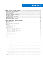
-ESD protection...6 ESD field service kit ...7 Transporting sensitive components...8 Exiting Service Mode...8 After working inside your computer...8 Chapter 2: Removing and installing components 9 Recommended tools...9 Screw list...9 Major components of Inspiron 13 5310...10 Base cover...12 - Dell Inspiron 13 5310 | Service Manual - Page 4
64 Clearing CMOS settings...64 Clearing BIOS (System Setup) and System passwords 65 Chapter 5: Troubleshooting...66 Locate the Service Tag or Express Service Code of your Dell computer 66 System-diagnostic lights...66 SupportAssist | On-board Diagnostics...67 Recovering the operating system - Dell Inspiron 13 5310 | Service Manual - Page 5
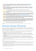
and press the power button for 3 seconds or until the Dell logo appears on the screen. 3. Press any key to continue any key to continue the Service Mode procedure. NOTE: The Service Mode procedure automatically skips the following the system board. Safety instructions Use the following safety - Dell Inspiron 13 5310 | Service Manual - Page 6
troubleshooting and repairs as authorized or directed by the Dell technical assistance team. Damage due to servicing that is not authorized by Dell is not covered by your warranty. See the safety instructions may not be obvious, such as intermittent problems or a shortened product life span. As the - Dell Inspiron 13 5310 | Service Manual - Page 7
for safe transport. ESD protection summary It is recommended that all field service technicians use the traditional wired ESD grounding wrist strap and protective anti-static mat at all times when servicing Dell products. In addition, it is critical that technicians keep sensitive parts separate - Dell Inspiron 13 5310 | Service Manual - Page 8
or parts to be returned to Dell, it is critical to place and point your toes out. 2. Tighten stomach muscles. Abdominal muscles support your spine when you lift, offsetting the force of the load. reverse to set the load down. Exiting Service Mode Service Mode allows users to immediately cut off - Dell Inspiron 13 5310 | Service Manual - Page 9
2 Removing and installing components NOTE: The images in this document may differ from your computer depending on the configuration you ordered. Recommended tools The procedures in this document may require the following tools: ● Phillips screwdriver #0 Screw list NOTE: When removing screws - Dell Inspiron 13 5310 | Service Manual - Page 10
Table 1. Screw list Component I/O board Touchpad Screw type M2x3 M2x2 Quantity 1 2 Screw image Touchpad bracket M2x2 4 Type-C port-bracket M2x4 2 Major components of Inspiron 13 5310 The following image shows the major components of Inspiron 13 5310. 10 Removing and installing components - Dell Inspiron 13 5310 | Service Manual - Page 11
and keyboard assembly 7. Display assembly 8. Coin-cell battery 9. Power-button with optional fingerprint reader 10. Left speaker 11. System board 12. Heat sink 13. Wireless-card bracket 14. Wireless card 15. Left fan 16. M.2 2280 solid-state drive, if installed 17. M.2 2230 solid-state drive, if - Dell Inspiron 13 5310 | Service Manual - Page 12
to warranty coverages purchased by the customer. Contact your Dell sales representative for purchase options. Base cover Removing the Prerequisites 1. Follow the procedure in Before working inside your computer. 2. Enter Service Mode. About this task NOTE: Before removing the base cover, ensure that - Dell Inspiron 13 5310 | Service Manual - Page 13
. About this task The following image(s) indicate the location of the base cover and provides a visual representation of the installation procedure. Removing and installing components 13 - Dell Inspiron 13 5310 | Service Manual - Page 14
) on the base cover. 3. Replace the five screws (M2x4) that secure the base cover to the palm-rest assembly. Next steps 1. Exit Service Mode. 2. Follow the procedure in After working inside your computer. Solid-state drive Removing the M.2 2230 solid-state drive Prerequisites 1. Follow the procedure - Dell Inspiron 13 5310 | Service Manual - Page 15
with an M.2 2230 solid-state drive installed. NOTE: The M.2 card installed on your computer will depend on the configuration ordered. The supported card configurations on the M.2 card slot are: ● M.2 2230 solid-state drive + 2230 mounting bracket ● M.2 2280 solid-state drive The following image - Dell Inspiron 13 5310 | Service Manual - Page 16
you are installing a M.2 2230 solid-state drive. NOTE: The M.2 card installed on your computer will depend on the configuration ordered. The supported card configurations on the M.2 card slot are: ● M.2 2230 solid-state drive + 2230 mounting bracket ● M.2 2280 solid-state drive The following image - Dell Inspiron 13 5310 | Service Manual - Page 17
the system board. Next steps 1. Install the base cover. 2. Exit Service Mode. 3. Follow the procedure in After working inside your computer. Removing card installed on your computer will depend on the configuration ordered. The supported card configurations on the M.2 card slota are: ● M.2 2230 solid - Dell Inspiron 13 5310 | Service Manual - Page 18
if you are installing a M.2 2280 solid-state drive. NOTE: The M.2 card installed on your computer will depend on the configuration ordered. The supported card configurations on the M.2 card slot are: ● M.2 2230 solid-state drive + 2230 mounting bracket ● M.2 2280 solid-state drive 18 Removing and - Dell Inspiron 13 5310 | Service Manual - Page 19
M.2 2280 solid-state drive to the palm-rest and keyboard assembly. 4. Place the Mylar over the system board. Next steps 1. Install the base cover. 2. Exit Service Mode. 3. Follow the procedure in After working inside your computer. Removing and installing components 19 - Dell Inspiron 13 5310 | Service Manual - Page 20
Wireless card Removing the wireless card Prerequisites 1. Follow the procedure in Before working inside your computer. 2. Enter Service Mode. 3. Remove the base cover. About this task The following image(s) indicate the location of the wireless card and provides a visual representation of the - Dell Inspiron 13 5310 | Service Manual - Page 21
5. Slide and remove the wireless card off the M.2 card slot on the system board. Installing the wireless card Prerequisites If you are replacing a component, remove the existing component before performing the installation process. About this task The following image(s) indicate the location of the - Dell Inspiron 13 5310 | Service Manual - Page 22
technical support for assistance. See www.dell.com/contactdell. ● Always purchase genuine batteries from www.dell.com or authorized Dell partners and resellers. Removing the battery Prerequisites 1. Follow the procedure in Before working inside your computer. 2. Enter Service Mode. 3. Remove the - Dell Inspiron 13 5310 | Service Manual - Page 23
Steps 1. Remove the five screws (M2x3) that secure the battery to the palm-rest and keyboard assembly. 2. Lift the battery off the palm-rest and keyboard assembly. 3. Disconnect the battery cable from the system board, if applicable. Installing the battery Prerequisites If you are replacing a - Dell Inspiron 13 5310 | Service Manual - Page 24
the five screws (M2x3) that secure the battery to the palm-rest and keyboard assembly. Next steps 1. Install the base cover. 2. Exit Service Mode. 3. Follow the procedure in After working inside your computer. Coin-cell battery Removing the coin-cell battery Prerequisites 1. Follow the procedure in - Dell Inspiron 13 5310 | Service Manual - Page 25
Steps 1. Disconnect the coin-cell battery from the system board. 2. Peel the tape that secures the coin-cell battery to the palm-rest and keyboard assembly. 3. Peel and lift the coin-cell battery from the palm-rest and keyboard assembly. Installing the coin-cell battery Prerequisites If you are - Dell Inspiron 13 5310 | Service Manual - Page 26
the tape the secures the coin-cell battery to the palm-rest and keyboard assembly. Next steps 1. Install the base cover. 2. Exit Service Mode. 3. Follow the procedure in After working inside your computer. Speakers Removing the speakers Prerequisites 1. Follow the procedure in Before working inside - Dell Inspiron 13 5310 | Service Manual - Page 27
board. 3. Peel off the tape that secures the speaker cable to the palm-rest and keyboard assembly. 4. Remove the speaker cable from the routing guides on the palm-rest and keyboard assembly. 5. Lift the right speaker from the palm-rest and keyboard assembly. 6. Remove the speaker cable from the - Dell Inspiron 13 5310 | Service Manual - Page 28
assembly. NOTE: Ensure that the alignment posts are threaded through the rubber grommets on the speaker. 2. Route the speaker cable through the routing guides on the palm-rest and keyboard assembly. 3. Using the alignment posts, place the right speaker on the palm-rest and keyboard assembly. NOTE - Dell Inspiron 13 5310 | Service Manual - Page 29
Fans Removing the left fan Prerequisites 1. Follow the procedure in Before working inside your computer. 2. Enter Service Mode. 3. Remove the base cover. About this task The following image(s) indicate the location of the left fan and provides a visual representation of the removal - Dell Inspiron 13 5310 | Service Manual - Page 30
the left-fan cable to the system board. 5. Adhere the Mylar over the system board. Next steps 1. Install the base cover. 2. Exit Service Mode. 3. Follow the procedure in After working inside your computer. Removing the right fan Prerequisites 1. Follow the procedure in Before working inside your - Dell Inspiron 13 5310 | Service Manual - Page 31
Steps 1. Peel the Mylar off the system board. 2. Remove the two screws (M2x3) that secure the right fan to the palm-rest and keyboard assembly. 3. Disconnect the right-fan cable from the system board. 4. Lift the right fan off the palm-rest and keyboard assembly. Installing the right fan - Dell Inspiron 13 5310 | Service Manual - Page 32
the right-fan cable to the system board. 5. Adhere the Mylar over the system board. Next steps 1. Install the base cover. 2. Exit Service Mode. 3. Follow the procedure in After working inside your computer. Touchpad Removing the touchpad Prerequisites 1. Follow the procedure in Before working inside - Dell Inspiron 13 5310 | Service Manual - Page 33
Steps 1. Open the latch and disconnect the touchpad cable from the system board. 2. Remove the four screws (M2x2) that secure the touchpad bracket to the palm-rest and keyboard assembly. 3. Lift the touchpad bracket off the palm-rest and keyboard assembly. 4. Remove the two screws (M2x2) that secure - Dell Inspiron 13 5310 | Service Manual - Page 34
inside your computer. Display assembly Removing the display assembly Prerequisites 1. Follow the procedure in Before working inside your computer. 2. Enter Service Mode. 3. Remove the base cover. About this task The following image(s) indicate the location of the display assembly and provides - Dell Inspiron 13 5310 | Service Manual - Page 35
Removing and installing components 35 - Dell Inspiron 13 5310 | Service Manual - Page 36
Steps 1. Peel the tape that secures the display-cable bracket to the system board. 2. Remove the screw (M2x3) that secures the display-cable bracket to the system board. 3. Lift the display-cable bracket off the system board. 4. Peel the tape that secures the display-cable connector latch to the - Dell Inspiron 13 5310 | Service Manual - Page 37
rest and keyboard assembly. CAUTION: To avoid damaging the display, do not slide the palm-rest and keyboard assembly over the display assembly. 13. After performing the above steps, you are left with the display assembly. Installing the display assembly Prerequisites If you are replacing a component - Dell Inspiron 13 5310 | Service Manual - Page 38
38 Removing and installing components - Dell Inspiron 13 5310 | Service Manual - Page 39
. Adhere the tape that secures the display-cable connector latch to the system board. 12. Place the display-cable bracket over the display-cable connector. 13. Align the screw hole on the display-cable bracket to the screw hole on the system board. Removing and installing components 39 - Dell Inspiron 13 5310 | Service Manual - Page 40
board. 15. Adhere the tape that secures the display-cable bracket to the system board. Next steps 1. Install the base cover. 2. Exit Service Mode. 3. Follow the procedure in After working inside your computer. I/O board Removing the I/O board Prerequisites 1. Follow the procedure in Before working - Dell Inspiron 13 5310 | Service Manual - Page 41
-rest and keyboard assembly. 8. Connect the I/O-board cable to the connector on the I/O board and close the latch. Next steps 1. Install the base cover. 2. Exit Service Mode. 3. Follow the procedure in After working inside your computer. Removing and installing components 41 - Dell Inspiron 13 5310 | Service Manual - Page 42
reader Removing the power-button with optional fingerprint reader Prerequisites 1. Follow the procedure in Before working inside your computer. 2. Enter Service Mode. 3. Remove the base cover. 4. Remove the left fan. 5. Remove the I/O board. About this task The following image(s) indicate the - Dell Inspiron 13 5310 | Service Manual - Page 43
in After working inside your computer. Heat sink Removing the heat sink Prerequisites 1. Follow the procedure in Before working inside your computer. 2. Enter Service Mode. 3. Remove the base cover. About this task NOTE: The heat sink may become hot during normal operation. Allow sufficient time for - Dell Inspiron 13 5310 | Service Manual - Page 44
The following image(s) indicate the location of the heat sink and provides a visual representation of the removal procedure. Steps 1. In reverse sequential order (7>6>5>4>3>2>1) loosen the seven captive screws (M2x2) that secure the heat sink to the system board. NOTE: The number of screws varies - Dell Inspiron 13 5310 | Service Manual - Page 45
. 2. In sequential order (1>2>3>4>5>6>7) tighten the seven captive screws (M2x2) that secure the heat sink to the system board. Next steps 1. Install the base cover. 2. Exit Service Mode. 3. Follow the procedure in After working inside your computer. Removing and installing components 45 - Dell Inspiron 13 5310 | Service Manual - Page 46
System board Removing the system board Prerequisites 1. Follow the procedure in Before working inside your computer. 2. Remove the base cover. 3. Remove the battery. 4. Remove the M.2 2230 solid-state drive or M.2 2280 solid-state drive, whichever applicable. 5. Remove the wireless card. 6. Remove - Dell Inspiron 13 5310 | Service Manual - Page 47
Lift the I/O-board cable-connector latch and disconnect the I/O-board cable from the system board. 12. Disconnect the speaker cable from the system board. 13. Lift the latch and disconnect the touchpad cable from the system board. 14. Lift the latch and disconnect the keyboard cable from the system - Dell Inspiron 13 5310 | Service Manual - Page 48
Steps 1. Place the system board on the palm-rest and keyboard assembly. 2. Align the screw holes on the system board with the screw holes on the palm-rest and keyboard assembly. 3. Close the right-display hinge and align the screw holes on the right-display hinge with the screw holes on the system - Dell Inspiron 13 5310 | Service Manual - Page 49
(M2x3) that secures the display-cable bracket to the system board. 12. Adhere the tape that secures the display-cable bracket to the system board. 13. Connect the power-button with fingerprint-reader cable to the connector on the system board and close the latch. 14. Connect the coin-cell battery - Dell Inspiron 13 5310 | Service Manual - Page 50
Steps After performing the pre-requisites you are left with the palm-rest and keyboard assembly. Installing the palm-rest and keyboard assembly Prerequisites If you are replacing a component, remove the existing component before performing the installation process. About this task The following - Dell Inspiron 13 5310 | Service Manual - Page 51
Steps Place the palm-rest and keyboard assembly on a flat and clean surface and perform the post-requisites to install the palm-rest and keyboard assembly. Next steps 1. Install the system board. 2. Install the power button. 3. Install the IO board. 4. Install the display assembly. 5. Install the - Dell Inspiron 13 5310 | Service Manual - Page 52
3 Drivers and downloads When troubleshooting, downloading or installing drivers it is recommended that you read the Dell Knowledge Based article, Drivers and Downloads FAQ SLN128938. 52 Drivers and downloads - Dell Inspiron 13 5310 | Service Manual - Page 53
4 System setup CAUTION: Unless you are an expert computer user, do not change the settings in the BIOS Setup program. Certain changes can make your computer work incorrectly. NOTE: Depending on the computer and its installed devices, the items listed in this section may or may not be displayed. - Dell Inspiron 13 5310 | Service Manual - Page 54
optical drive or hard drive). During the Power-on Self Test (POST), when the Dell logo appears, you can: ● Access System Setup by pressing F2 key ● Bring up Overview BIOS Version Displays the BIOS version number. Service Tag Displays the Service Tag of the computer. Asset Tag Displays the - Dell Inspiron 13 5310 | Service Manual - Page 55
Table 4. System setup options-System information menu Overview Processor ID Displays the processor identification code. Processor L2 Cache Displays the processor L2 Cache size. Processor L3 Cache Displays the processor L3 Cache size. Microcode Version Displays the microcode version. Intel - Dell Inspiron 13 5310 | Service Manual - Page 56
or disables booting from USB mass storage devices such as external hard drive, optical drive, and USB drive. By default, Enable USB Boot Support is selected. Table 7. System setup options-Storage menu (continued) Storage SATA/NVMe Operation SATA/NVMe Operation Configures operating mode of the - Dell Inspiron 13 5310 | Service Manual - Page 57
to boot within the number of failures equal or greater than the value specified by Dell Auto OS Recovery Threshold, and local Service does not boot, or is not installed. Default: ON Dell Auto OS Recovery Threshold Controls the automatic boot flow for SupportAssist System Resolution Console and - Dell Inspiron 13 5310 | Service Manual - Page 58
of the computer hardware will always halt the computer. Table 13. System setup options-System Logs menu System Logs BIOS dell.com/support. ● Enter the Service Tag or Express Service Code and click Search. ● Click Drivers & Downloads. ● Click Detect Drivers and follow the on-screen instructions - Dell Inspiron 13 5310 | Service Manual - Page 59
only THIS PC XXXXXXX. NOTE: XXXXXXX denotes the Service Tag. 9. Select the latest BIOS file and click file. NOTE: Follow the on-screen instructions. Updating BIOS on systems with BitLocker enabled see Knowledge Article: https:// www.dell.com/support/article/sln153694 Updating your system BIOS using - Dell Inspiron 13 5310 | Service Manual - Page 60
will need: ● USB key formatted to the FAT32 file system (key does not have to be bootable) ● BIOS executable file that you downloaded from the Dell Support website and copied to the root of the USB key ● AC power adapter connected to the system ● Functional system battery to flash the BIOS Perform - Dell Inspiron 13 5310 | Service Manual - Page 61
3. The flash BIOS menu will open, and then click the Flash from file. 4. Select external USB device. System setup 61 - Dell Inspiron 13 5310 | Service Manual - Page 62
5. Once the file is selected, Double click the flash target file, then press submit. 6. Click the Update BIOS then system will reboot to flash the BIOS. 62 System setup - Dell Inspiron 13 5310 | Service Manual - Page 63
7. Once complete, the system will reboot and the BIOS update process is completed. System and setup password Table 14. System and setup password Password type System password Setup password Description Password that you must enter to log in to your system. Password that you must enter to access - Dell Inspiron 13 5310 | Service Manual - Page 64
computer restarts. Clearing CMOS settings About this task CAUTION: Clearing CMOS settings will reset the BIOS settings on your computer. Steps 1. Enter Service Mode. 2. Remove the base cover. 3. Remove the coin-cell battery. 4. Wait for one minute. 5. Replace the coin-cell battery. 6. Replace the - Dell Inspiron 13 5310 | Service Manual - Page 65
Clearing BIOS (System Setup) and System passwords About this task To clear the system or BIOS passwords, contact Dell technical support as described at www.dell.com/contactdell. NOTE: For information on how to reset Windows or application passwords, refer to the documentation accompanying Windows or - Dell Inspiron 13 5310 | Service Manual - Page 66
codes and recommended solutions are intended for Dell service technicians to troubleshoot problems. You should only perform troubleshooting and repairs as authorized or directed by the Dell technical support team. Damage due to servicing that is not authorized by Dell is not covered by your warranty - Dell Inspiron 13 5310 | Service Manual - Page 67
. Diagnostic-light codes Diagnostic light codes (Amber, white) Problem description 2,4 Memory or RAM (Random-Access Memory) failure the tests are completed successfully ● View error messages that indicate if problems were encountered during the test NOTE: Some tests for specific devices - Dell Inspiron 13 5310 | Service Manual - Page 68
website to troubleshoot and fix your computer when it fails to boot into their primary operating system due to software or hardware failures. For more information about the Dell SupportAssist OS Recovery, see Dell SupportAssist OS Recovery User's Guide at www.dell.com/support. Flashing BIOS (USB - Dell Inspiron 13 5310 | Service Manual - Page 69
to WiFi connectivity issues a WiFi power cycle procedure may be performed. The following procedure provides the instructions on how to conduct a WiFi power cycle: NOTE: Some ISPs (Internet Service Providers) provide a modem/router combo device. Steps 1. Turn off your computer. 2. Turn off the modem - Dell Inspiron 13 5310 | Service Manual - Page 70
and services www.dell.com My Dell Tips Contact Support Online help for operating system In Windows search, type Contact Support, and press Enter. www.dell.com/support/windows www.dell.com/support/linux Troubleshooting information, user manuals, setup instructions, www.dell.com/support product
-
 1
1 -
 2
2 -
 3
3 -
 4
4 -
 5
5 -
 6
6 -
 7
7 -
8
-
9
-
10
-
11
-
12
-
13
-
14
-
15
-
16
-
17
-
18
-
19
-
20
-
21
-
22
-
23
-
24
-
25
-
26
-
27
-
28
-
29
-
30
-
31
-
32
-
33
-
34
-
35
-
36
-
37
-
38
-
39
-
40
-
41
-
42
-
43
-
44
-
45
-
46
-
47
-
48
-
49
-
50
-
51
-
52
-
53
-
54
-
55
-
56
-
57
-
58
-
59
-
60
-
61
-
62
-
63
-
64
-
65
-
66
-
67
-
68
-
69
-
70
 |
 |

Inspiron 13 5310
Service Manual
Regulatory Model: P145G
Regulatory Type: P145G001
March 2021
Rev. A00