Dell Inspiron 620 Service Manual
Dell Inspiron 620 Manual
 |
View all Dell Inspiron 620 manuals
Add to My Manuals
Save this manual to your list of manuals |
Dell Inspiron 620 manual content summary:
- Dell Inspiron 620 | Service Manual - Page 1
Dell™ Inspiron™ 620s Service Manual Technical Overview Before You Begin Computer Cover Memory Module(s) Front Bezel PCI Express Cards Card Retention Bracket Drives Front I/O Panel Power Button Module Fans Processor Coin-Cell Battery Power Supply System Board System Setup Flashing the BIOS Notes, - Dell Inspiron 620 | Service Manual - Page 2
to Contents Page Before You Begin Dell™ Inspiron™ 620s Service Manual Technical Specifications Recommended Tools Turning Off Your Computer Safety Instructions This manual provides instructions for removing and installing the components in your computer. Unless otherwise noted, each procedure assumes - Dell Inspiron 620 | Service Manual - Page 3
all telephone or network cables from the computer. 4. Disconnect your computer and all attached devices from their electrical outlets. 5. Disconnect all attached devices from your computer. 6. Press and eject any installed cards from the Media Card Reader. 7. Press and hold the power button - Dell Inspiron 620 | Service Manual - Page 4
Back to Contents Page Front Bezel Dell™ Inspiron™ 620s Service Manual Removing the Front Bezel Replacing the Front Bezel WARNING: Before working inside your computer, read the safety information that shipped with your computer. For additional safety best practices information, see the Regulatory - Dell Inspiron 620 | Service Manual - Page 5
into the front panel slots. 3. Rotate the front bezel towards the computer until the front bezel tabs snap into place. 1 front bezel 2 front bezel tabs (3) 3 front bezel clamps (4) 4 front panel slots (4) 5 front panel 4. Replace the computer cover (see Replacing the Computer Cover). Back to - Dell Inspiron 620 | Service Manual - Page 6
the BIOS Dell™ Inspiron™ 620s Service Manual The BIOS may require flashing when an update is available or when replacing the system board. To flash the BIOS: 1. Turn on the computer. 2. Go to support.dell.com/support/downloads. 3. Locate the BIOS update file for your computer. NOTE: The Service Tag - Dell Inspiron 620 | Service Manual - Page 7
Dell™ Inspiron™ 620s Service Manual Removing PCI Express Cards Replacing PCI Express Cards Configuring Your Computer After Removing or Installing the PCI Express Card WARNING: Before working inside your computer, read the safety information that shipped with your computer. For additional safety best - Dell Inspiron 620 | Service Manual - Page 8
dust and dirt out of your computer. Replacing PCI Express Cards 1. Follow the instructions in Before You Begin. 2. Prepare the card for installation. See the documentation that shipped with the card for information on configuring the card, making internal connections, or otherwise customizing it for - Dell Inspiron 620 | Service Manual - Page 9
1 PCI Express x1 card 2 PCI Express x1 card slot PCI Express x16 card: - The securing tab on the PCI Express x16 card slot may vary based on your computer model. Perform one of the following instructions based on the type of securing tab on the PCI Express x16 card slot. l Push the securing tab to - Dell Inspiron 620 | Service Manual - Page 10
the computer cover (see Replacing the Computer Cover). 7. Reconnect the computer and devices to electrical outlets, and then turn them on. 8. To complete the installation, see Configuring Your Computer After Removing or Installing the PCI Express Card. Configuring Your Computer After Removing or - Dell Inspiron 620 | Service Manual - Page 11
Page Card Retention Bracket Dell™ Inspiron™ 620s Service Manual Removing the Card Retention Bracket Replacing the Card Retention Bracket WARNING: Before working inside your computer, read the safety information that shipped with your computer. For additional safety best practices information - Dell Inspiron 620 | Service Manual - Page 12
1 release tab 2 card retention bracket Back to Contents Page - Dell Inspiron 620 | Service Manual - Page 13
to Contents Page Coin-Cell Battery Dell™ Inspiron™ 620s Service Manual Removing the Coin-Cell Battery Replacing the Coin-Cell Battery WARNING: Before working inside your computer, read the safety information that shipped with your computer. For additional safety best practices information, see the - Dell Inspiron 620 | Service Manual - Page 14
1 coin-cell battery 2 battery socket 3. Replace the computer cover (see Replacing the Computer Cover). 4. Connect your computer and devices to electrical outlets, and then turn them on. 5. Enter system setup (see System Setup) and restore the settings you recorded in step 1. Back to Contents Page - Dell Inspiron 620 | Service Manual - Page 15
Back to Contents Page Computer Cover Dell™ Inspiron™ 620s Service Manual Removing the Computer Cover Replacing the Computer Cover WARNING: Before working inside your computer, read the safety information that shipped with your computer. For additional safety best practices information, see the - Dell Inspiron 620 | Service Manual - Page 16
5. Press the computer cover down and slide it towards the front of the computer. 6. Using a screwdriver, replace the two screws that secure the computer cover to the chassis. 1 computer cover 3 slots 2 screws (2) 7. Place the computer in an upright position. Back to Contents Page - Dell Inspiron 620 | Service Manual - Page 17
Back to Contents Page Processor Dell™ Inspiron™ 620s Service Manual Removing the Processor Replacing the Processor WARNING: Before working inside your computer, read the safety information that shipped with your computer. For additional safety best practices information, see the Regulatory - Dell Inspiron 620 | Service Manual - Page 18
at the back of the computer. CAUTION: When replacing the processor, do not touch avoid permanent damage to the processor and the computer when you turn on the computer. 3. If the release lever on the indicator CAUTION: Ensure that the processor cover notch is positioned underneath the alignment post - Dell Inspiron 620 | Service Manual - Page 19
Fan and Heat-Sink Assembly). CAUTION: Ensure that the processor fan and heat-sink assembly is correctly seated and secure. 11. Replace the computer cover (see Replacing the Computer Cover). 12. Connect your computer and devices to electrical outlets, and turn them on. Back to Contents Page - Dell Inspiron 620 | Service Manual - Page 20
to Contents Page Drives Dell™ Inspiron™ 620s Service Manual Hard Drive Optical Drive WARNING: Before working inside your computer, read the safety information that shipped with your computer. For additional safety best practices information, see the Regulatory Compliance Homepage at www.dell.com - Dell Inspiron 620 | Service Manual - Page 21
Follow the instructions in Before You Begin. 2. Remove the hard-drive assembly (see Removing the Hard-Drive Assembly). 3. Pull the tabs on the hard-drive bezel outwards and lift the hard-drive off the hard-drive bezel. 1 hard-drive bezel 3 hard drive 2 tabs (4) Replacing the Hard-Drive Bezel - Dell Inspiron 620 | Service Manual - Page 22
the tab on the hard-drive assembly until the hard-drive assembly snaps into position. 5. Connect the power and data cables to the hard drive. 6. Replace the computer cover (see Replacing the Computer Cover). 7. Connect your computer and devices to electrical outlets, and then turn them on. 8. See - Dell Inspiron 620 | Service Manual - Page 23
the power and data cables to the optical drive. 5. Replace the front bezel (see Replacing the Front Bezel). 6. Replace the computer cover (see Replacing the Computer Cover). 7. Connect your computer and devices to electrical outlets, and turn them on. 8. See the documentation that shipped with - Dell Inspiron 620 | Service Manual - Page 24
Back to Contents Page Fans Dell™ Inspiron™ 620s Service Manual Chassis Fan Processor Fan and Heat-Sink Assembly WARNING: Before working inside your computer, read the safety information that shipped with your computer. For additional safety best practices information, see the Regulatory Compliance - Dell Inspiron 620 | Service Manual - Page 25
System Board Components). 5. Replace the computer cover (see Replacing the Computer Cover). Processor Fan and Heat remove the fan separately. Removing the Processor Fan and Heat-Sink Assembly 1. Follow the instructions in Before You Begin. 2. Remove the computer cover (see Removing the Computer Cover - Dell Inspiron 620 | Service Manual - Page 26
is correctly seated and secure. 7. Connect the processor fan cable to the system board connector, FAN_CPU (see System Board Components). 8. Replace the computer cover (see Replacing the Computer Cover). 9. Connect your computer and devices to electrical outlets, and turn them on. Back to Contents - Dell Inspiron 620 | Service Manual - Page 27
Back to Contents Page Front I/O Panel Dell™ Inspiron™ 620s Service Manual Removing the Front I/O Panel Replacing the Front I/O Panel WARNING: Before working inside your computer, read the safety information that shipped with your computer. For additional safety best practices information, see the - Dell Inspiron 620 | Service Manual - Page 28
board connectors, AUDIOF1, USBF1, and USBF2 (see System Board Components). 5. Replace the front bezel (see Replacing the Front Bezel). 6. Replace the computer cover (see Replacing the Computer Cover). 7. Connect your computer and devices to electrical outlets, and turn them on. Back to Contents Page - Dell Inspiron 620 | Service Manual - Page 29
Back to Contents Page Memory Module(s) Dell™ Inspiron™ 620s Service Manual Removing the Memory Module(s) Replacing the Memory Module(s) WARNING: Before working inside your computer, read the safety information that shipped with your computer. For additional safety best practices information, see the - Dell Inspiron 620 | Service Manual - Page 30
at each end of the memory module. 1 cutouts (2) 2 securing clips (2 ; snapped in position) 5. Replace the computer cover (see Replacing the Computer Cover). 6. Connect your computer and devices to electrical outlets, and then turn them on. If a message appears stating that the memory size has - Dell Inspiron 620 | Service Manual - Page 31
Back to Contents Page Power Supply Dell™ Inspiron™ 620s Service Manual Removing the Power Supply Replacing the Power Supply WARNING: Before working inside your computer, read the safety information that shipped with your computer. For additional safety best practices information, see the Regulatory - Dell Inspiron 620 | Service Manual - Page 32
secure the power supply to the chassis. 5. Connect the DC power cables to the system board and drives (see System Board Components). 6. Replace the computer cover (see Replacing the Computer Cover). 7. Connect your computer and devices to electrical outlets, and turn them on. Back to Contents Page - Dell Inspiron 620 | Service Manual - Page 33
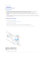
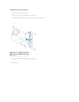
Page Power Button Module Dell™ Inspiron™ 620s Service Manual Removing the Power Button Module Replacing the Power Button Module WARNING: Before working inside your computer, read the safety information that shipped with your computer. For additional safety best practices information, see the - Dell Inspiron 620 | Service Manual - Page 34
cable to the system board connector, LEDH1 (see System Board Components). 4. Replace the front bezel (see Replacing the Front Bezel). 5. Replace the computer cover (see Replacing the Computer Cover). 6. Connect your computer and devices to electrical outlets and turn them on. Back to Contents Page - Dell Inspiron 620 | Service Manual - Page 35
Page System Board Dell™ Inspiron™ 620s Service Manual Removing the System Board Replacing the System Board Entering the Service Tag in the BIOS WARNING: Before working inside your computer, read the safety information that shipped with your computer. For additional safety best practices information - Dell Inspiron 620 | Service Manual - Page 36
, if applicable (see Replacing PCI Express Cards). 9. Replace the computer cover (see Replacing the Computer Cover). 10. Connect your computer and devices to electrical outlets and turn them on. 11. Flash the system BIOS, as needed (see Flashing the BIOS). 12. Enter the service tag (see Entering the - Dell Inspiron 620 | Service Manual - Page 37
Page System Setup Dell™ Inspiron™ 620s Service Manual Overview Clearing Forgotten Passwords Clearing CMOS Passwords Overview Use the system setup to: l Change the system configuration information after you add, change, or remove any hardware in your computer l Set or change a user-selectable option - Dell Inspiron 620 | Service Manual - Page 38
drive connected to the SATA 2 connector SATA 3 Displays the SATA drive connected to the SATA 3 connector Advanced CPU Configuration Graphics Configuration System Configuration Power Management Post Behavior l Hyper-threading - Enabled or Disabled (Enabled by default) l Active Processor Cores - Dell Inspiron 620 | Service Manual - Page 39
CD/DVD/CD-RW drive to run the Dell Diagnostics from the Drivers and Utilities disc. On completion of diagnostic tests, the previous boot sequence is restored. 1. If you are booting from a USB device, connect the USB device to a USB connector. 2. Turn on (or restart) your computer. 3. When F2 Setup - Dell Inspiron 620 | Service Manual - Page 40
from their electrical outlets. 7. Remove the 2-pin jumper plug from pins 1 and 2 and replace it on pins 2 and 3 to enable the password feature. 8. Replace the computer cover (see Replacing the Computer Cover). 9. Connect your computer and devices to electrical outlets and turn them on. Clearing CMOS - Dell Inspiron 620 | Service Manual - Page 41
approximately five seconds to clear the CMOS setting. 6. Remove the 2-pin jumper plug from pins 1 and 2 and replace it on pins 2 and 3. 7. Replace the computer cover (see Replacing the Computer Cover). 8. Connect your computer and devices to electrical outlets and turn them on. Back to Contents Page - Dell Inspiron 620 | Service Manual - Page 42
to Contents Page Technical Overview Dell™ Inspiron™ 620s Service Manual Inside View of Your Computer System Board Components WARNING: Before working inside your computer, read the safety information that shipped with your computer. For additional safety best practices information, see the Regulatory - Dell Inspiron 620 | Service Manual - Page 43
internal speaker connector (INTSPKR1) 10 chassis fan connector (FAN_SYS1) 12 SATA drive connector (SATA 0) 14 CMOS reset jumper (CMOSCLR1) 16 front panel USB connector (USBF1) 18 front panel audio connector (AUDIOF1) 20 PCI Express x1 card slot (SLOT3) 22 battery socket (BT1) Back to Contents Page
-
 1
1 -
 2
2 -
 3
3 -
 4
4 -
 5
5 -
 6
6 -
 7
7 -
8
-
9
-
10
-
11
-
12
-
13
-
14
-
15
-
16
-
17
-
18
-
19
-
20
-
21
-
22
-
23
-
24
-
25
-
26
-
27
-
28
-
29
-
30
-
31
-
32
-
33
-
34
-
35
-
36
-
37
-
38
-
39
-
40
-
41
-
42
-
43
 |
 |
Dell™ Inspiron™ 620s Service Manual
Notes, Cautions, and Warnings
Information in this document is subject to change without notice.
© 2011 Dell Inc. All rights reserved.
Reproduction of these materials in any manner whatsoever without the written permission of Dell Inc. is strictly forbidden.
Trademarks used in this text: Dell™, the DELL logo, and Inspiron
-
™ are trademarks of Dell Inc.; Microsoft®
, Windows
®
,
and the Windows start button logo
are either
trademarks or registered trademarks of Microsoft Corporation in the United States and/or other countries.
Other trademarks and trade names may be used in this document to refer to either the entities claiming the marks and names or their products. Dell Inc. disclaims any
proprietary interest in trademarks and trade names other than its own.
2011 -
05
Rev. A00
Regulatory model: D06D series
Regulatory type: D06D001
Technical Overview
Before You Begin
Computer Cover
Memory Module(s)
Front Bezel
PCI Express Cards
Card Retention Bracket
Drives
Front I/O Panel
Power Button Module
Fans
Processor
Coin
-
Cell Battery
Power Supply
System Board
System Setup
Flashing the BIOS
NOTE:
A NOTE indicates important information that helps you make better use of your computer.
CAUTION:
A CAUTION indicates either potential damage to hardware or loss of data and tells you how to avoid the problem.
WARNING:
A WARNING indicates a potential for property damage, personal injury, or death.