Dell Inspiron 620 Service Manual - Page 26
System Board Components, Replacing the Computer Cover, Back to Contents
 |
View all Dell Inspiron 620 manuals
Add to My Manuals
Save this manual to your list of manuals |
Page 26 highlights
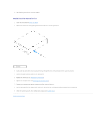
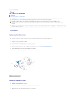
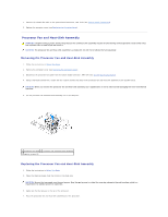
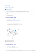
5. Align the four captive screws on the processor fan and heat-sink assembly with the screw holes on the system board. 6. Tighten the four captive screws that secure the processor fan and heat-sink assembly to the system board. NOTE: Ensure that the processor fan and heat-sink assembly is correctly seated and secure. 7. Connect the processor fan cable to the system board connector, FAN_CPU (see System Board Components). 8. Replace the computer cover (see Replacing the Computer Cover). 9. Connect your computer and devices to electrical outlets, and turn them on. Back to Contents Page
-
 1
1 -
2
-
3
-
4
-
5
-
6
-
7
-
8
-
9
-
10
-
11
-
12
-
13
-
14
-
15
-
16
-
17
-
18
-
19
-
20
-
 21
21 -
 22
22 -
 23
23 -
 24
24 -
 25
25 -
 26
26 -
 27
27 -
 28
28 -
 29
29 -
 30
30 -
 31
31 -
32
-
33
-
34
-
35
-
36
-
37
-
38
-
39
-
40
-
41
-
42
-
43
 |
 |

5.
Align the four captive screws on the processor fan and heat-sink assembly with the screw holes on the system board.
6.
Tighten the four captive screws that secure the processor fan and heat-sink assembly to the system board.
7.
Connect the processor fan cable to the system board connector, FAN_CPU (see
System Board Components
).
8.
Replace the computer cover (see
Replacing the Computer Cover
).
9.
Connect your computer and devices to electrical outlets, and turn them on.
Back to Contents Page
NOTE:
Ensure that the processor fan and heat-sink assembly is correctly seated and secure.