Dell Inspiron 7405 2-in-1 Inspiron 7405 2n1 Service Manual - Page 49
Palm-rest and keyboard assembly
 |
View all Dell Inspiron 7405 2-in-1 manuals
Add to My Manuals
Save this manual to your list of manuals |
Page 49 highlights
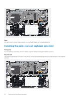
5. Connect the power-adapter port cable to the connector on the system board. 6. Align the screw holes on the USB Type-C port bracket with the screw holes on the system board. 7. Adhere the tape that secures the USB Type-C port bracket to the system board. 8. Replace the two screws (M2x3) that secure the USB Type-C port bracket to the system board. 9. Connect the keyboard cable to the connector on the system board and close the latch to secure the cable. 10. Connect the touchpad cable to the connector on the system board and close the latch to secure the cable. 11. Connect the speaker cable to the system board. 12. Connect the I/O-board cable to the connector on the system board and close the latch to secure the cable. 13. Adhere the tape that secures the I/O-board cable to the system board. 14. Connect the fan cable to the system board. 15. Close the right display hinge. 16. Replace the three screws (M2.5x5) that secure the right display hinge to the system board. Next steps 1. Install the heat sink. 2. Install the fan. 3. Install the M.2 2230 solid-state drive or M.2 2280 solid-state drive, as applicable. 4. Install the memory modules. 5. Install the coin-cell battery. 6. Install the battery. 7. Install the base cover. 8. Follow the procedure in After working inside your computer. Palm-rest and keyboard assembly Removing the palm-rest and keyboard assembly Prerequisites 1. Follow the procedure in Before working inside your computer. 2. Remove the base cover. 3. Remove the battery. 4. Remove the coin-cell battery. 5. Remove the memory modules. 6. Remove the M.2 2230 solid-state drive or M.2 2280 solid-state drive, as applicable. 7. Remove the I/O board. 8. Remove the speakers. 9. Remove the heat sink. 10. Remove the fan. 11. Remove the touchpad. 12. Remove the power-adapter port. 13. Remove the power-button board. 14. Remove the display assembly. 15. Remove the system board. NOTE: The system board can be removed or installed together with the heat sink attached. This simplifies the procedure and avoids breaking the thermal bond between the system board and the heat sink. About this task The following image indicates the location of the palm-rest and keyboard assembly and provides a visual representation of the removal procedure. Removing and installing components 49
-
 1
1 -
2
-
3
-
4
-
5
-
6
-
7
-
8
-
9
-
10
-
11
-
12
-
13
-
14
-
15
-
16
-
17
-
18
-
19
-
20
-
21
-
22
-
23
-
24
-
25
-
26
-
27
-
28
-
29
-
30
-
31
-
32
-
33
-
34
-
35
-
36
-
37
-
38
-
39
-
40
-
41
-
42
-
43
-
 44
44 -
 45
45 -
 46
46 -
 47
47 -
 48
48 -
 49
49 -
 50
50 -
 51
51 -
 52
52 -
 53
53 -
 54
54 -
55
-
56
-
57
-
58
-
59
-
60
-
61
-
62
-
63
 |
 |
