Dell Latitude 3330 Owner's Manual - Page 26
Installing The Input/Output (I/O) Board, Removing The Power Connector
 |
View all Dell Latitude 3330 manuals
Add to My Manuals
Save this manual to your list of manuals |
Page 26 highlights
Installing The Input/Output (I/O) Board 1. Insert the I/O board into its slot. 2. Connect the speaker cable to the I/O board. 3. Install: a) system board b) palmrest c) memory d) hard drive e) keyboard f) base cover g) secure digital (SD) card h) battery 4. Follow the procedures in After Working Inside Your Computer. Removing The Power Connector 1. Follow the procedures in Before Working on Your Computer. 2. Remove: a) battery b) secure digital (SD) card c) base cover d) hard drive e) palmrest f) memory g) keyboard h) display assembly i) system board 3. Remove the screw that secures the power connector port. 4. Lift up and remove the power connector port from the bottom base. 26
-
 1
1 -
2
-
3
-
4
-
5
-
6
-
7
-
8
-
9
-
10
-
11
-
12
-
13
-
14
-
15
-
16
-
17
-
18
-
19
-
20
-
 21
21 -
 22
22 -
 23
23 -
 24
24 -
 25
25 -
 26
26 -
 27
27 -
 28
28 -
 29
29 -
 30
30 -
 31
31 -
32
-
33
-
34
-
35
-
36
-
37
-
38
-
39
-
40
-
41
-
42
-
43
-
44
-
45
-
46
-
47
-
48
-
49
-
50
-
51
-
52
-
53
 |
 |
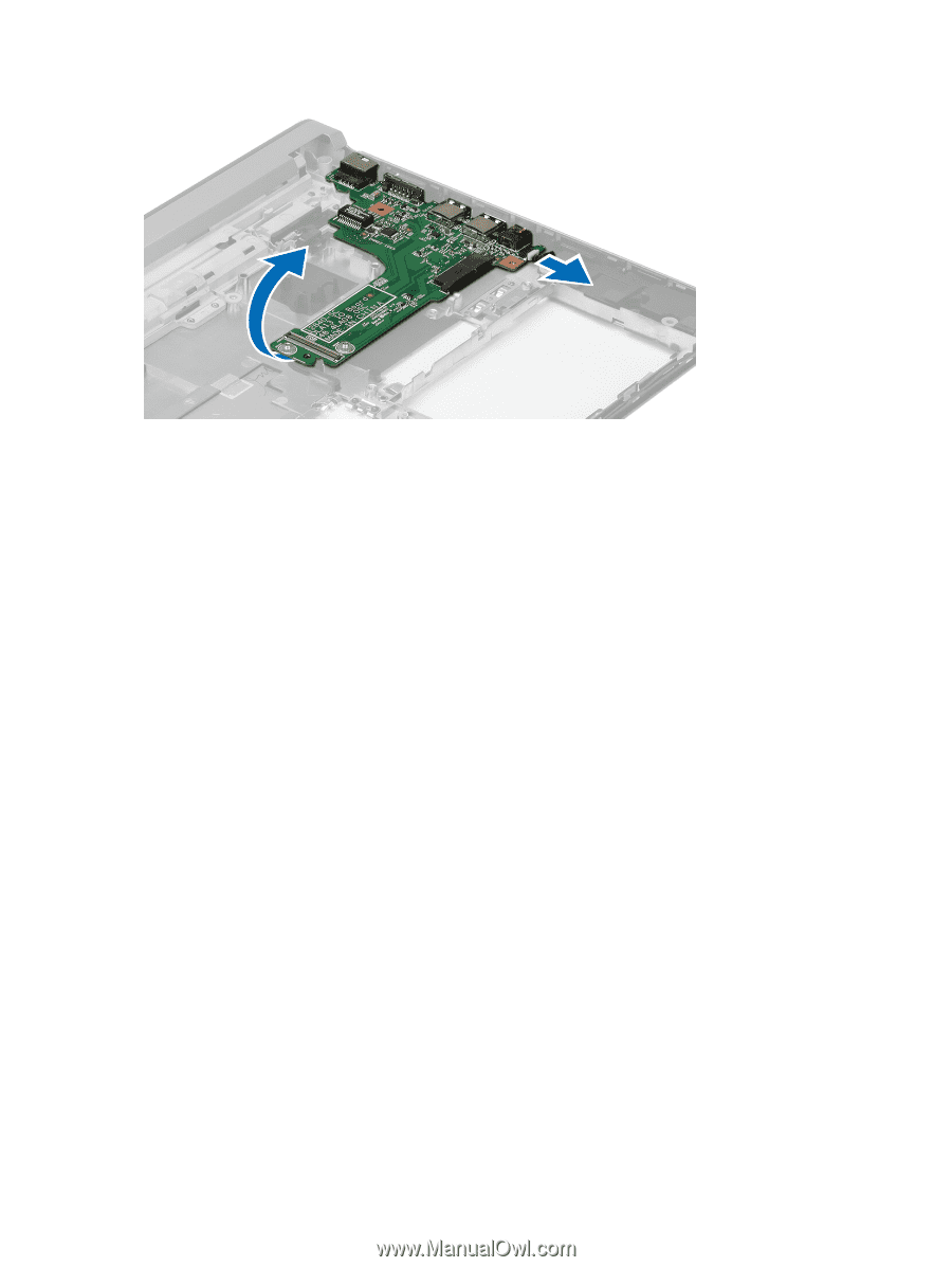
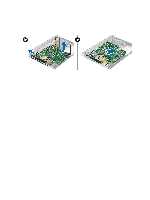
Installing The Input/Output (I/O) Board
1.
Insert the I/O board into its slot.
2.
Connect the speaker cable to the I/O board.
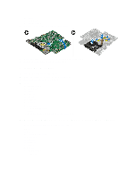
3.
Install:
a)
system board
b)
palmrest
c)
memory
d)
hard drive
e)
keyboard
f)
base cover
g)
secure digital (SD) card
h)
battery
4.
Follow the procedures in
After Working Inside Your Computer
.
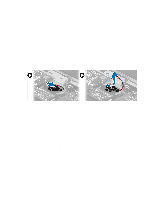
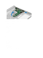
Removing The Power Connector
1.
Follow the procedures in
Before Working on Your Computer
.
2.
Remove:
a)
battery
b)
secure digital (SD) card
c)
base cover
d)
hard drive
e)
palmrest
f)
memory
g)
keyboard
h)
display assembly
i)
system board
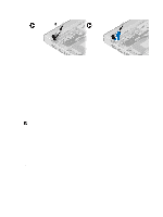
3.
Remove the screw that secures the power connector port.
4.
Lift up and remove the power connector port from the bottom base.
26