Dell Latitude D630 XFR User's Guide - Page 82
Removing the Handle, Installing the Handle
 |
View all Dell Latitude D630 XFR manuals
Add to My Manuals
Save this manual to your list of manuals |
Page 82 highlights
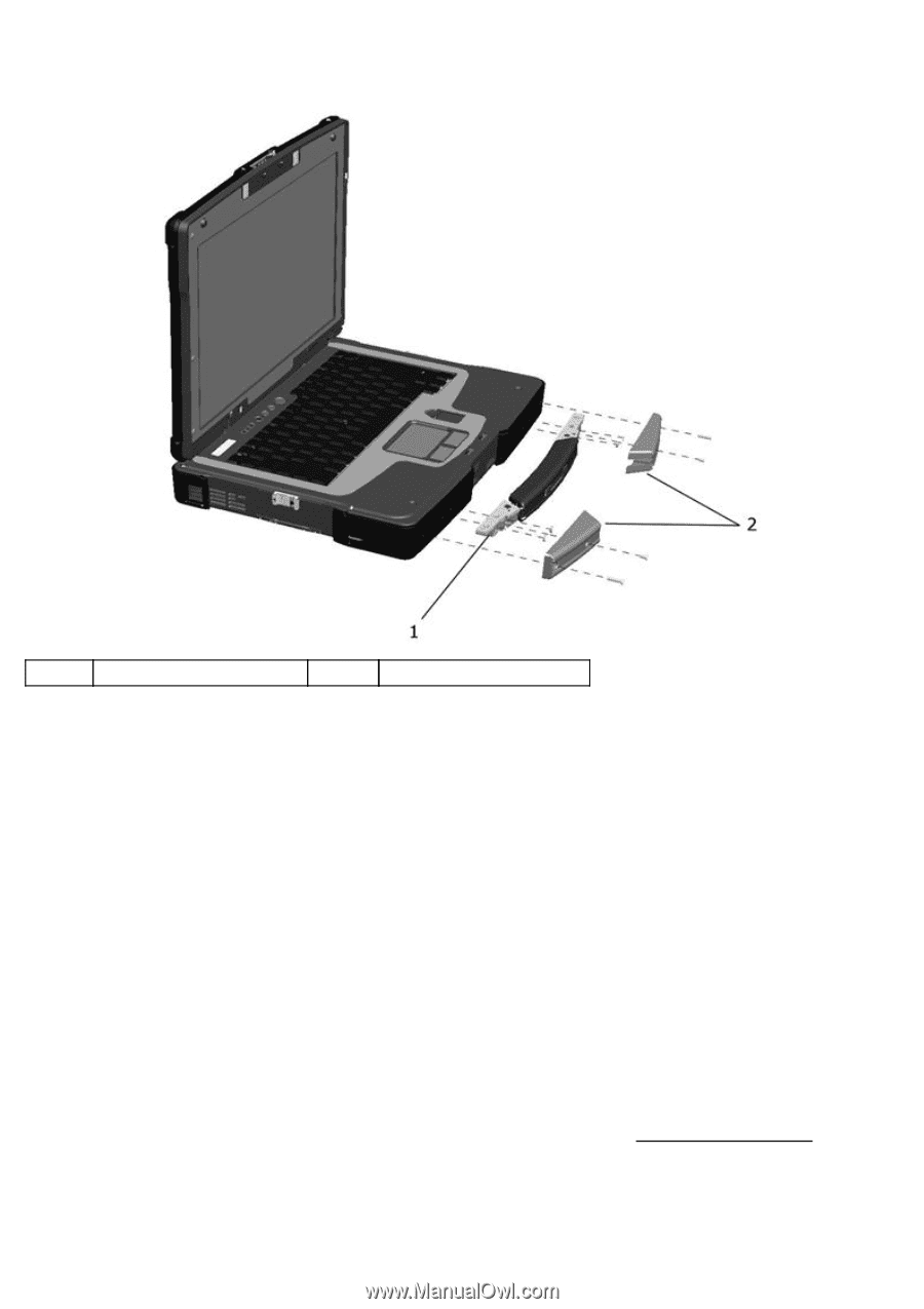
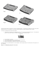
the handle if replacement is required. Figure 14 10 Installation of the XFR D630 Handle Assembly 1 Main handle assembly 2 Handle cover (2) 14.8.1 Removing the Handle 1. Remove the 4 screws (2 on each handle cover) that secure the handle covers as shown in the figure above. 2. Remove the 6 screws (3 on each side) on the top of the handle assembly that secure the handle to the handle brackets. 3. Remove the 6 screws (3 on each side) that secure the main handle assembly. 14.8.2 Installing the Handle 1. Align the main handle assembly with the mounting holes in the front plate of the XFR D630 as shown in the figure above. 2. Secure the main handle assembly to the XFR D630 using the 6 screws provided. 3. Install the 6 screws (3 on each side) on the top of the handle assembly that secure the handle to the handle brackets. 4. Align each of the handle covers over the main handle assembly ends as shown. 5. If your XFR D630 is equipped with the optional Touch Screen, please refer to Replacing the Stylus Clip for 309H instructions regarding installing the stylus clip onto one side of the handle assembly. 6. Secure the handle covers over the main handle assembly and to the XFR D630 with the 4 screws provided (2 on each side).
-
 1
1 -
2
-
3
-
4
-
5
-
6
-
7
-
8
-
9
-
10
-
11
-
12
-
13
-
14
-
15
-
16
-
17
-
18
-
19
-
20
-
21
-
22
-
23
-
24
-
25
-
26
-
27
-
28
-
29
-
30
-
31
-
32
-
33
-
34
-
35
-
36
-
37
-
38
-
39
-
40
-
41
-
42
-
43
-
44
-
45
-
46
-
47
-
48
-
49
-
50
-
51
-
52
-
53
-
54
-
55
-
56
-
57
-
58
-
59
-
60
-
61
-
62
-
63
-
64
-
65
-
66
-
67
-
68
-
69
-
70
-
71
-
72
-
73
-
74
-
75
-
76
-
 77
77 -
 78
78 -
 79
79 -
 80
80 -
 81
81 -
 82
82 -
 83
83 -
 84
84 -
 85
85 -
 86
86 -
 87
87 -
88
-
89
-
90
-
91
-
92
-
93
-
94
-
95
-
96
-
97
-
98
-
99
-
100
-
101
-
102
-
103
-
104
-
105
-
106
 |
 |