Dell OptiPlex GL Service Manual - Page 19
Power Distribution, core regulator
 |
View all Dell OptiPlex GL manuals
Add to My Manuals
Save this manual to your list of manuals |
Page 19 highlights
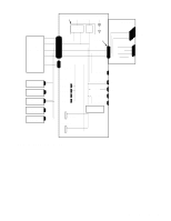
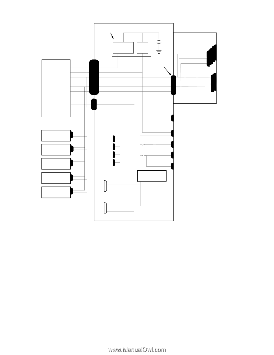
keyboard controller system board +3 VDC system power supply P1 PWRGOOD PSON# +5 VFP +5 VDC -5 VDC +12 VDC -12 VDC POWER1 power management logic PSON# +5 VFP +5 VDC -5 VDC +12 VDC -12 VDC RTC/ NVRAM battery RISER +5 VDC -5 VDC +12 VDC -12 VDC riser board +5 VDC +12 VDC -12 VDC +5 VDC -5 VDC +12 VDC -12 VDC PCI1 through PCI5 ISA1, ISA2 P7 +3.3 VDC POWER2 +12 VDC FAN optional P2 drive optional P3 drive P4 3.5-inch diskette drive P5 internal hard-disk drive P6 internal hard-disk drive main memory sockets DIMM_A DIMM_B DIMM_C DIMM_D MICROPROCESSOR +2.1-3.5 VDC +3.3 VDC +5 VFP +5 VDC FUSE +5 VDC FUSE +5 VDC +5 VDC processor core regulator 2ND_CPU +2.1-3.5 VDC +3.3 VDC PANEL USB KYBD MOUSE Figure 1-9. Power Distribution System Overview 1-11
-
 1
1 -
2
-
3
-
4
-
5
-
6
-
7
-
8
-
9
-
10
-
11
-
12
-
13
-
 14
14 -
 15
15 -
 16
16 -
 17
17 -
 18
18 -
 19
19 -
 20
20 -
 21
21 -
 22
22 -
 23
23 -
 24
24 -
25
-
26
-
27
-
28
-
29
-
30
-
31
-
32
-
33
-
34
-
35
-
36
-
37
-
38
-
39
-
40
-
41
-
42
-
43
-
44
-
45
-
46
-
47
-
48
-
49
-
50
-
51
-
52
-
53
-
54
-
55
-
56
-
57
-
58
-
59
-
60
-
61
-
62
-
63
-
64
-
65
-
66
-
67
-
68
-
69
-
70
-
71
-
72
-
73
-
74
-
75
-
76
-
77
-
78
-
79
-
80
 |
 |
System Overview
1-11
Figure 1-9.
Power Distribution
P3
+5 VDC
+12 VDC
–12 VDC
+12 VDC
+12 VDC
–12 VDC
3.5-inch
diskette drive
system
power supply
PSON#
+5 VFP
+5 VDC
–5 VDC
+12 VDC
–12 VDC
PWRGOOD
PSON#
+5 VFP
+5 VDC
–5 VDC
+12 VDC
–12 VDC
power
management
logic
keyboard
controller
battery
+3 VDC
P1
POWER1
+5 VDC
–5 VDC
+12 VDC
–12 VDC
+5 VDC
–5 VDC
ISA1,
ISA2
PCI1
through
PCI5
MICROPROCESSOR
+5 VDC
+5 VDC
+5 VDC
+5 VDC
PANEL
USB
KYBD
MOUSE
DIMM_A
DIMM_B
DIMM_C
DIMM_D
main memory
sockets
P4
FAN
RISER
internal
hard-disk drive
P2
optional
drive
P5
P6
+5 VFP
RTC/
NVRAM
P7
+3.3 VDC
2ND_CPU
riser board
system board
optional
drive
internal
hard-disk drive
POWER2
+3.3 VDC
processor
core regulator
+2.1–3.5 VDC
+3.3 VDC
+2.1–3.5 VDC
FUSE
FUSE