Dell Optiplex 9010 All In One Dell OptiPlex 9010 All-In-One Touch Owner's Manu - Page 33
Installing the System Board, Memory connector SODIMM socket B
 |
View all Dell Optiplex 9010 All In One manuals
Add to My Manuals
Save this manual to your list of manuals |
Page 33 highlights
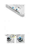
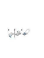
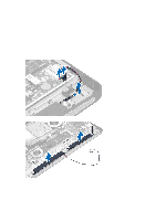
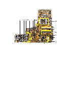
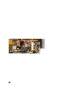
1. PSU connector 2. PSU fan connector 3. Touch panel connector 4. Power button board connector 5. SATA HDD connector 6. SATA HDD power connector 7. SATA ODD power connector 8. CPU fan connector 9. SATA ODD connector 10. LVDS connector 11. 12V CPU power connector 12. Processor socket 13. Memory connector (SODIMM socket B) 14. Memory connector (SODIMM socket A) 15. Intrusion switch connector 16. Mini-PCI socket 17. Internal speaker connector 18. Coin-cell battery connector 19. Converter board connector Installing the System Board 1. Place the system board on the computer. 2. Tighten the screws to secure the system board to the base panel. 33
-
 1
1 -
2
-
3
-
4
-
5
-
6
-
7
-
8
-
9
-
10
-
11
-
12
-
13
-
14
-
15
-
16
-
17
-
18
-
19
-
20
-
21
-
22
-
23
-
24
-
25
-
26
-
27
-
 28
28 -
 29
29 -
 30
30 -
 31
31 -
 32
32 -
 33
33 -
 34
34 -
 35
35 -
 36
36 -
 37
37 -
 38
38 -
39
-
40
-
41
-
42
-
43
-
44
-
45
-
46
-
47
-
48
-
49
-
50
-
51
-
52
-
53
-
54
-
55
-
56
-
57
-
58
-
59
-
60
-
61
-
62
-
63
-
64
-
65
-
66
-
67
 |
 |
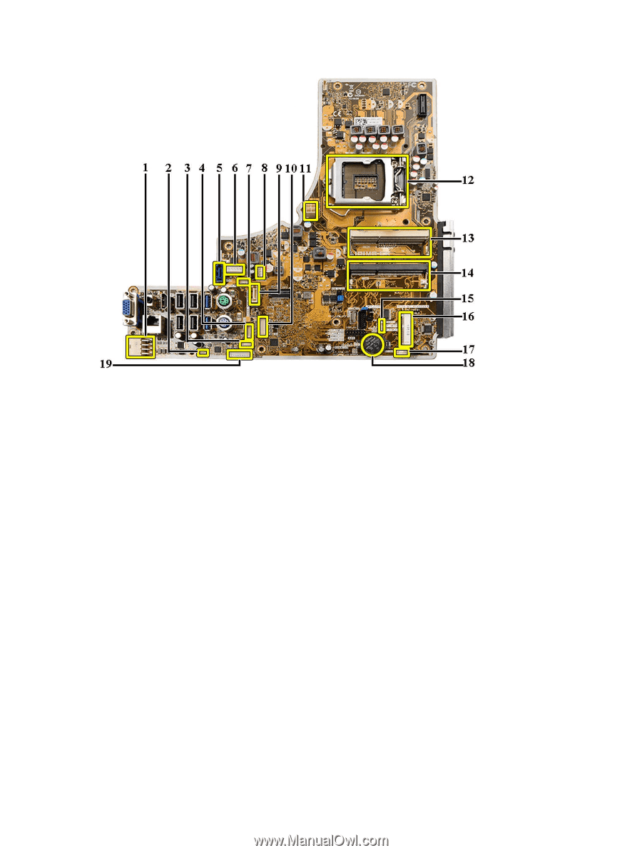
1. PSU connector
2. PSU fan connector
3. Touch panel connector
4. Power button board connector
5. SATA HDD connector
6. SATA HDD power connector
7. SATA ODD power connector
8. CPU fan connector
9. SATA ODD connector
10. LVDS connector
11. 12V CPU power connector
12. Processor socket
13. Memory connector (SODIMM socket B)
14. Memory connector (SODIMM socket A)
15. Intrusion switch connector
16. Mini-PCI socket
17. Internal speaker connector
18. Coin-cell battery connector
19. Converter board connector
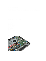
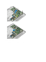
Installing the System Board
1.
Place the system board on the computer.
2.
Tighten the screws to secure the system board to the base panel.
33