Dell PowerEdge 1800 Information Update (.pdf) - Page 17
Attaching the System Stabilizer Feet, Position each stabilizer foot as shown
 |
View all Dell PowerEdge 1800 manuals
Add to My Manuals
Save this manual to your list of manuals |
Page 17 highlights
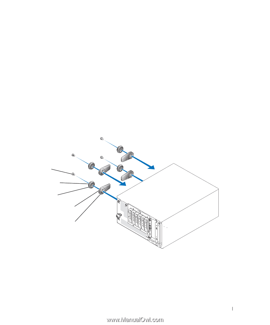
Attaching the System Stabilizer Feet 1 Locate a stabilizer foot, a circular swivel disk, and a Phillips screw from the rack-to-tower kit. 2 Place the circular swivel disk inside the circular cavity on the bottom of the stabilizer foot and rotate it until it seats completely inside the cavity. The swivel disk properly seats inside the cavity when the inner-disk tab on the swivel disk inserts into the swivel slot on the stabilizer foot. See Figure 1-13. 3 Attach the stabilizer feet to the left side of the chassis: a Position each stabilizer foot as shown in Figure 1-13. b Insert the inner-disk tab on the swivel disk into the slot in the chassis. c Secure the stabilizer foot to the chassis with a Phillips screw. 4 Repeat step 1 through step 3 to attach the other three stabilizer feet. Figure 1-13. Attaching the System Stabilizer Feet securing screws (4) swivel disks (4) inner-disk tab system stabilizer feet (4) swivel slot Installing the Tower-to-Rack and Rack-to-Tower Kits 15
-
 1
1 -
2
-
3
-
4
-
5
-
6
-
7
-
8
-
9
-
10
-
11
-
 12
12 -
 13
13 -
 14
14 -
 15
15 -
 16
16 -
 17
17 -
 18
18 -
 19
19 -
 20
20
 |
 |