Dell PowerEdge 1900 Hardware Owner's Manual (PDF) - Page 128
Table 6-2., System Board Connectors, Connector, Description, TCP/IP Offload Engine Key - raid battery
 |
View all Dell PowerEdge 1900 manuals
Add to My Manuals
Save this manual to your list of manuals |
Page 128 highlights
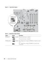
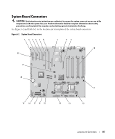
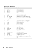
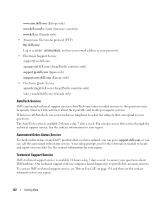
Table 6-2. System Board Connectors Item Connector 1 PCIE_X4_6 2 PCIE_X4_5 3 PCIE_X4_4 4 PCIE_X8_3 5 PCIX_2 6 PCIX_1 7 INT_STORAGE 8 RAC_CONN 9 RAC_MII_CONN 10 DIMMn 11 FANn 12 CPU1 13 CPU2 14 PWRn 15 SATA_x 16 PWR_CTRL 17 FLOPPY 18 IDE 19 CONTROL_PANEL 20 BATTERY 21 TOE_KEY 22 HD_ACT_CARD Description PCIe x4 connector (slot 6) PCIe x4 connector (slot 5) PCIe x4 connector (slot 4) PCIe x8 connector (slot 3) PCI-X 64-bit connectors (slot 2) PCI-X 64-bit connectors (slot 1) SAS RAID controller daughter card connector Connector for the remote access controller (RAC) RAC MII connector Memory module connector (8), numbered by population order (see "Memory" on page 80) Fan power connector (6) Processor connector 1 Processor connector 2 Power supply connector (2) SATA connectors (4) Power supply connector Floppy disk drive connector CD-ROM connector Control panel connector Connector for the 3.0-V coin battery TCP/IP Offload Engine Key Hard drive activity indicator connector for SAS RAID controller daughter card and SAS controller card 128 Jumpers and Connectors
-
 1
1 -
2
-
3
-
4
-
5
-
6
-
7
-
8
-
9
-
10
-
11
-
12
-
13
-
14
-
15
-
16
-
17
-
18
-
19
-
20
-
21
-
22
-
23
-
24
-
25
-
26
-
27
-
28
-
29
-
30
-
31
-
32
-
33
-
34
-
35
-
36
-
37
-
38
-
39
-
40
-
41
-
42
-
43
-
44
-
45
-
46
-
47
-
48
-
49
-
50
-
51
-
52
-
53
-
54
-
55
-
56
-
57
-
58
-
59
-
60
-
61
-
62
-
63
-
64
-
65
-
66
-
67
-
68
-
69
-
70
-
71
-
72
-
73
-
74
-
75
-
76
-
77
-
78
-
79
-
80
-
81
-
82
-
83
-
84
-
85
-
86
-
87
-
88
-
89
-
90
-
91
-
92
-
93
-
94
-
95
-
96
-
97
-
98
-
99
-
100
-
101
-
102
-
103
-
104
-
105
-
106
-
107
-
108
-
109
-
110
-
111
-
112
-
113
-
114
-
115
-
116
-
117
-
118
-
119
-
120
-
121
-
122
-
 123
123 -
 124
124 -
 125
125 -
 126
126 -
 127
127 -
 128
128 -
 129
129 -
 130
130 -
 131
131 -
 132
132 -
 133
133 -
134
-
135
-
136
-
137
-
138
-
139
-
140
-
141
-
142
-
143
-
144
-
145
-
146
-
147
-
148
-
149
-
150
-
151
-
152
-
153
-
154
-
155
-
156
-
157
-
158
-
159
-
160
-
161
-
162
-
163
-
164
-
165
-
166
 |
 |