Dell PowerEdge 6350 Dell PowerEdge Systems 6350 Installation and Troubleshooti - Page 133
See Removing the Front Bezel
 |
View all Dell PowerEdge 6350 manuals
Add to My Manuals
Save this manual to your list of manuals |
Page 133 highlights
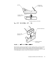
2. Prepare the drive for installation. Ground yourself by touching an unpainted metal surface on the back of the computer, unpack the drive, and compare the jumper and switch settings with those in the drive documentation. (See "CD-ROM Drive Configuration" found earlier in this chapter for information on setting the drive's SCSI ID number and disabling termination [if needed].) Change any settings necessary for this system's configuration. If the drive does not already have drive rails attached, attach a drive rail to each side of the drive. Orient the drive rails as shown in Figure 9-5. Secure each drive rail to the drive with a screw in each of the lower slotted screw holes on the drive rail. latch tabs 3. Remove the front bezel. See "Removing the Front Bezel" in Chapter 7. 4. Slide the new drive into its bay until the latch tabs snap securely into place. If necessary, you can adjust drive alignment by repositioning one or both rails. 5. Connect a DC power cable and the Ultra/Narrow SCSI cable to the back of the drive (see Figure 9-1). Refer to "DC Power Cables," found earlier in this chapter, to determine the correct DC power cable connector to use for the drive. Plug the DC power cable connector into the 4-pin power input connector on the back of the drive. 6. Check all cable connections that may have been loosened during this procedure. Arrange cables so that they will not catch on the computer covers or block the airflow of the fans or cooling vents. Installing the Diskette and CD-ROM Drives 9-5
-
 1
1 -
2
-
3
-
4
-
5
-
6
-
7
-
8
-
9
-
10
-
11
-
12
-
13
-
14
-
15
-
16
-
17
-
18
-
19
-
20
-
21
-
22
-
23
-
24
-
25
-
26
-
27
-
28
-
29
-
30
-
31
-
32
-
33
-
34
-
35
-
36
-
37
-
38
-
39
-
40
-
41
-
42
-
43
-
44
-
45
-
46
-
47
-
48
-
49
-
50
-
51
-
52
-
53
-
54
-
55
-
56
-
57
-
58
-
59
-
60
-
61
-
62
-
63
-
64
-
65
-
66
-
67
-
68
-
69
-
70
-
71
-
72
-
73
-
74
-
75
-
76
-
77
-
78
-
79
-
80
-
81
-
82
-
83
-
84
-
85
-
86
-
87
-
88
-
89
-
90
-
91
-
92
-
93
-
94
-
95
-
96
-
97
-
98
-
99
-
100
-
101
-
102
-
103
-
104
-
105
-
106
-
107
-
108
-
109
-
110
-
111
-
112
-
113
-
114
-
115
-
116
-
117
-
118
-
119
-
120
-
121
-
122
-
123
-
124
-
125
-
126
-
127
-
 128
128 -
 129
129 -
 130
130 -
 131
131 -
 132
132 -
 133
133 -
 134
134 -
 135
135 -
 136
136 -
 137
137 -
 138
138 -
139
-
140
-
141
-
142
-
143
-
144
-
145
-
146
-
147
-
148
-
149
-
150
-
151
-
152
-
153
-
154
-
155
-
156
-
157
-
158
-
159
-
160
-
161
-
162
-
163
-
164
-
165
-
166
-
167
-
168
-
169
-
170
-
171
-
172
-
173
-
174
-
175
-
176
-
177
-
178
-
179
-
180
-
181
-
182
-
183
-
184
-
185
-
186
-
187
-
188
-
189
-
190
-
191
-
192
-
193
-
194
-
195
-
196
-
197
-
198
-
199
-
200
-
201
-
202
-
203
-
204
-
205
 |
 |
