Dell PowerEdge C6220 Hardware Owner's Manual - Page 213
See
 |
View all Dell PowerEdge C6220 manuals
Add to My Manuals
Save this manual to your list of manuals |
Page 213 highlights
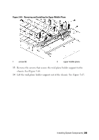
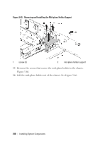
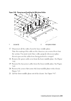
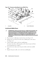
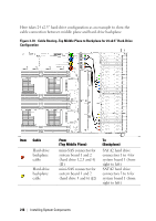
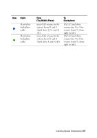
6 Place the middle plane holder into the chassis. See Figure 3-66. 7 Replace the screws that secure the middle plane holder to the chassis. See Figure 3-66. 8 Place the mid-plane holder support into the chassis. See Figure 3-65. 9 Replace the screws that secure the mid-plane holder support to the chassis. See Figure 3-65. 10 Place the upper middle plane on the mid-plane holder. See Figure 3-64. 11 Replace the screws that secure the middle plane to the middle plane holder. See Figure 3-64. 12 Connect all the cables to the upper middle plane. You must route these cables properly on the chassis to prevent them from being pinched or crimped. 13 Secure the screws that secure the power cables to the upper middle plane. 14 Replace the power cable cover to the upper lower middle plane. 15 Place the middle-wall bracket into the chassis. See Figure 3-61. 16 Replace the screws that secure the middle-wall bracket to the chassis. Figure 3-61. 17 Replace the cooling-fan cage. See Figure 3-52. 18 Replace the cooling fans. See "Installing a Cooling Fan" on page 194. 19 Replace the system-board assemblies. See "Installing a System-Board Assembly" on page 125. 20 Close the system, see "Closing the System" on page 191. 21 Reconnect the system to its electrical outlet and turn on the system, including any attached peripherals. Installing System Components | 213
-
 1
1 -
2
-
3
-
4
-
5
-
6
-
7
-
8
-
9
-
10
-
11
-
12
-
13
-
14
-
15
-
16
-
17
-
18
-
19
-
20
-
21
-
22
-
23
-
24
-
25
-
26
-
27
-
28
-
29
-
30
-
31
-
32
-
33
-
34
-
35
-
36
-
37
-
38
-
39
-
40
-
41
-
42
-
43
-
44
-
45
-
46
-
47
-
48
-
49
-
50
-
51
-
52
-
53
-
54
-
55
-
56
-
57
-
58
-
59
-
60
-
61
-
62
-
63
-
64
-
65
-
66
-
67
-
68
-
69
-
70
-
71
-
72
-
73
-
74
-
75
-
76
-
77
-
78
-
79
-
80
-
81
-
82
-
83
-
84
-
85
-
86
-
87
-
88
-
89
-
90
-
91
-
92
-
93
-
94
-
95
-
96
-
97
-
98
-
99
-
100
-
101
-
102
-
103
-
104
-
105
-
106
-
107
-
108
-
109
-
110
-
111
-
112
-
113
-
114
-
115
-
116
-
117
-
118
-
119
-
120
-
121
-
122
-
123
-
124
-
125
-
126
-
127
-
128
-
129
-
130
-
131
-
132
-
133
-
134
-
135
-
136
-
137
-
138
-
139
-
140
-
141
-
142
-
143
-
144
-
145
-
146
-
147
-
148
-
149
-
150
-
151
-
152
-
153
-
154
-
155
-
156
-
157
-
158
-
159
-
160
-
161
-
162
-
163
-
164
-
165
-
166
-
167
-
168
-
169
-
170
-
171
-
172
-
173
-
174
-
175
-
176
-
177
-
178
-
179
-
180
-
181
-
182
-
183
-
184
-
185
-
186
-
187
-
188
-
189
-
190
-
191
-
192
-
193
-
194
-
195
-
196
-
197
-
198
-
199
-
200
-
201
-
202
-
203
-
204
-
205
-
206
-
207
-
 208
208 -
 209
209 -
 210
210 -
 211
211 -
 212
212 -
 213
213 -
 214
214 -
 215
215 -
 216
216 -
 217
217 -
 218
218 -
219
-
220
-
221
-
222
-
223
-
224
-
225
-
226
-
227
-
228
-
229
-
230
-
231
-
232
-
233
-
234
-
235
-
236
-
237
-
238
-
239
-
240
-
241
-
242
-
243
-
244
-
245
-
246
-
247
-
248
-
249
-
250
-
251
-
252
-
253
-
254
-
255
-
256
-
257
-
258
-
259
-
260
-
261
-
262
-
263
-
264
-
265
-
266
-
267
-
268
-
269
-
270
-
271
-
272
-
273
-
274
 |
 |