Dell PowerEdge M1000e Technical Guide - Page 23
Control Panel/LCD
 |
View all Dell PowerEdge M1000e manuals
Add to My Manuals
Save this manual to your list of manuals |
Page 23 highlights
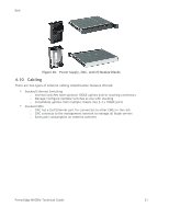
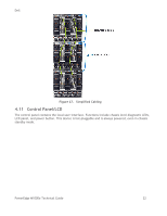
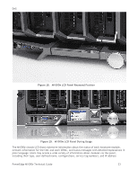
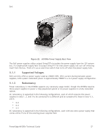
Dell Figure 17. Simplified Cabling 4.11 Control Panel/LCD The control panel contains the local user interface. Functions include chassis level diagnostic LEDs, LCD panel, and power button. This device is hot-pluggable and is always powered, even in chassis standby mode. PowerEdge M1000e Technical Guide 22
-
 1
1 -
2
-
3
-
4
-
5
-
6
-
7
-
8
-
9
-
10
-
11
-
12
-
13
-
14
-
15
-
16
-
17
-
 18
18 -
 19
19 -
 20
20 -
 21
21 -
 22
22 -
 23
23 -
 24
24 -
 25
25 -
 26
26 -
 27
27 -
 28
28 -
29
-
30
-
31
-
32
-
33
-
34
-
35
-
36
-
37
-
38
-
39
-
40
-
41
-
42
-
43
-
44
-
45
-
46
-
47
-
48
-
49
-
50
-
51
-
52
-
53
-
54
-
55
-
56
-
57
-
58
-
59
-
60
-
61
-
62
-
63
-
64
-
65
-
66
-
67
-
68
-
69
-
70
-
71
-
72
-
73
 |
 |

Dell
PowerEdge M1000e Technical Guide
22
Figure 17.
Simplified Cabling
4.11
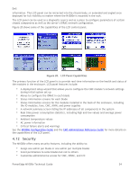
Control Panel/LCD
The control panel contains the local user interface. Functions include chassis level diagnostic LEDs,
LCD panel, and power button. This device is hot-pluggable and is always powered, even in chassis
standby mode.